KTA141001 Ver. 1.00
- 16 - Installation manual for PV modules
3. WARNING
Do not stand or step on the PV module (Glass and Terminal box).
4-1. ELECTRICAL OUTPUT
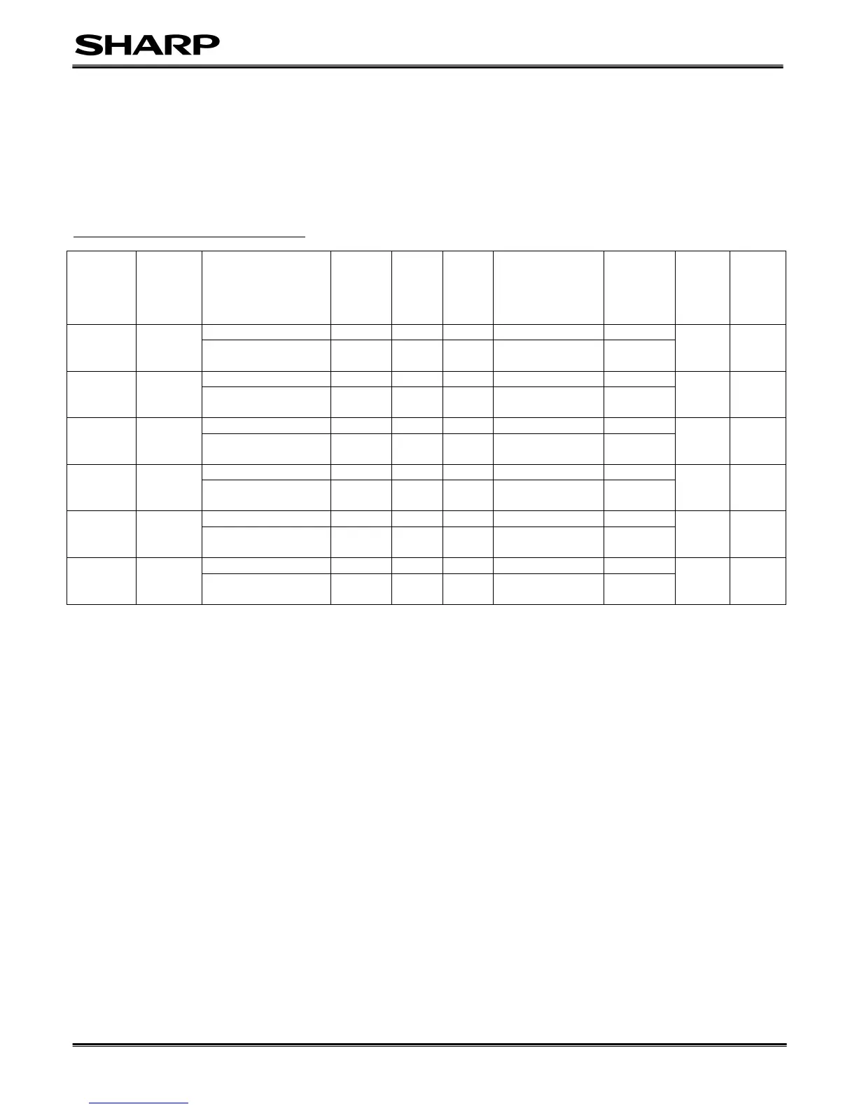
(for NA-E140L5, NA-E135L5, NA-E130L5, NA-E125L5, NA-E120L5, NA-E115L5)
Rated electrical characteristics of Isc and Voc are within ±10 percent of the indicated values and +7/-2 percent of Pmax under STC (standard test
conditions) (irradiance of 1000 W/m
2
, AM 1.5 spectrum, and a cell temperature of 25 °C (77°F). “Terms of guaranty” are specified separately.
Table-1-1. Electrical characteristics (at STC)
(*1)Tandem: amorphous silicon / microcrystalline silicon tandem structure cell
The number of modules in series configuration has to be chosen on the local conditions considering 1000V, maximum system voltage.
Under normal conditions, a photovoltaic module is likely to experience conditions that produce more current and/or voltage than reported at
Standard Test Conditions. Accordingly, the values of Isc and Voc marked on this module should be multiplied by a factor of 1.25 when determining
component voltage ratings, conductor capacities, fuse sizes and size of controls connected to the module output.
<For US market>
The maximum system voltage is 600V based on UL1703.
Under normal conditions, a PV module may produce more current and/or voltage than reported at Standard Test Conditions. Accordingly, the values
of Isc and Voc marked on UL 1703 listed modules should be multiplied by a factor of Voc=1.11 and Isc=1.30 at conditions of an irradiance of 125
mW/cm2, AM1.5 spectrum, and a cell temperature of minus 10 degree C (plus 14 degree F) for Voc and plus 75 degree C (167 degree F) for Isc
when determining component voltage ratings, conductor capacities, fuse sizes and size of controls connected to the module output.
Refer to Sec. 690-8 of the National Electric Code for an additional multiplying factor of Voc=111% and Isc=130% (80 percent de-rating) which may
be applicable.
Where Canadian UL listing applies, installation shall be in accordance with CSA C22.1, Safety Standard for Electrical Installations, Canadian
Electrical Code, Part 1.
5. Fire Class rating
Fire Class C
 Loading...