Do you have a question about the Sharp NU-JC400B and is the answer not in the manual?
Consult local codes, use qualified personnel, and follow safety practices for installation.
Wear protective gear, use insulated tools, and follow procedures to avoid shock or injury.
Mounting PV modules using clamps requires adherence to specific dimensions and secure frame support.
Modules can be fastened using frame bolt holes with M8 bolts and recommended torque.
Details on conductor size, cable type, voltage, and temperature ratings for electrical connections.
Specifies required connectors (MC4) and brand for PV module connections.
Keep PV modules and electrical connectors clean and dry before installation.
Proper disposal of PV modules should be done according to local recycling guidelines.
Specifies test loads for clamps on long frames according to IEC61215.
Specifies design loads for clamps on long frames according to IEC61215.
Specifies test loads for clamps on short frames according to IEC61215.
Specifies design loads for clamps on short frames according to IEC61215.
Specifies test loads for clamps on long and short frames according to IEC61215.
Specifies design loads for clamps on long and short frames according to IEC61215.
Specifies test loads using bolt holes for mounting according to IEC61215.
Specifies design loads using bolt holes for mounting according to IEC61215.
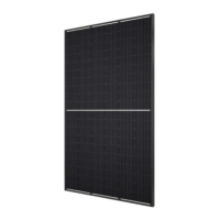
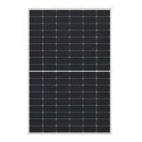
This document serves as an installation manual for a Crystalline Photovoltaic Module, specifically the SHARP NU-JC400B model. It provides essential information for the electrical and mechanical installation of these PV modules, along with crucial safety guidelines. The manual emphasizes that all information presented is the intellectual property of SHARP, based on their extensive technological and experiential history. SHARP disclaims responsibility for any loss, damage, or expense arising from the installation, operation, use, or maintenance of the PV modules, and reserves the right to modify the product, specifications, or manual without prior notice.
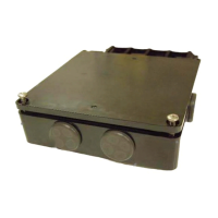
The SHARP NU-JC400B Crystalline Photovoltaic Module is designed to convert sunlight into electricity. These modules are equipped with permanently attached junction boxes that accommodate various wiring applications or come with special cable assemblies for easy installation, eliminating the need for special assembly. The modules can be wired in series to increase voltage, or in parallel to increase current, allowing for flexible system configurations to meet different power requirements. When connected in series, the voltage is cumulative, and when connected in parallel, the current is cumulative. A large-scale PV system can thus produce significant voltage and current. The PV modules are designed for long life and optimal electrical performance when mounted on rigid support structures. They are also equipped with anti-reflective coating glass to enhance efficiency.
The installation of these PV modules requires a high degree of skill and should only be performed by qualified licensed professionals, including contractors and electricians, due to the serious risk of injury, including electric shock. The manual stresses the importance of understanding all information before attempting installation, wiring, operation, or maintenance.
For optimal performance, PV modules should be installed in a location free from shading throughout the year. In the Northern Hemisphere, modules typically face south, and in the Southern Hemisphere, they face north. Special considerations and preventive measures are advised for installations in areas with heavy snow, extreme cold, strong winds, near water, or in corrosive environments.
The tilt angle of the PV module, measured between the module and a horizontal ground surface, is crucial for maximizing power output. A tilt angle of 5 degrees or more is recommended for maintenance purposes. For standalone systems with batteries, the tilt angle should optimize performance during periods of scarce sunlight. For grid-connected installations, tilting the module at an angle equal to the installation site's latitude is recommended for year-round optimal power generation.
Proper cable connection polarity is vital for system operation and to maintain the product's guarantee, as incorrect connections can damage bypass diodes. The modules can be mounted using clamps or by fastening them with bolts through designated holes in the frame. When using clamps, they must meet specified dimensions and hold the module frame completely within its width. For bolt-hole mounting, four M8 bolts are recommended with a specific torque.
The PV modules are designed to withstand significant mechanical loads, having passed tests for positive and negative loading. However, the system designer is responsible for ensuring protective structures can bear loads beyond standard test conditions. The mounting structure must be rigid, with no corner displacement exceeding 2mm per 1000mm of the diagonal, and allow the module to deflect freely under wind/snow load without direct impact to the module's center.
The PV modules are designed for minimal maintenance due to their long lifespan. If the tilt angle is 5 degrees or more, normal rainfall is usually sufficient to keep the glass surface clean. However, if dirt accumulation becomes excessive, cleaning should be done with a soft, damp cloth and water. Chemical cleaners should not be used on the glass surface, and water should not be allowed to collect on the glass for extended periods, as this can lead to "white efflorescence" (glass disease) and deteriorate energy generation.
The back sheet of the PV module should be handled with utmost care during cleaning to prevent damage. Regular checks of wiring connections and the condition of wire jackets are recommended to ensure proper system operation. Due to the anti-reflective coating, direct touching of the glass should be avoided to prevent fingerprints or stains. If excessive dirt accumulates, cleaning with water only is advised.
In case of extreme snow build-up, preventive measures such as snow stoppers should be taken to prevent the snow's weight from deforming the PV module frame. Periodically removing overhanging snow and/or ice from the framework is also necessary to prevent deformation.
The manual also outlines important safety precautions for maintenance, including wearing protective headgear, insulating gloves, and safety shoes, and avoiding metallic jewelry. Servicing should only be performed by qualified personnel. After any service or repair, routine checks should be performed to ensure the PV modules are in safe and proper operating condition. When replacement parts are needed, only manufacturer-specified parts with identical characteristics should be used to avoid hazards.
| Product Type | Control Unit |
|---|---|
| Model | NU-JC400B |
| Brand | Sharp |
| Frequency | 50/60 Hz |
| Weight | 6.5 kg |
| Power Supply | AC |
| Operating Humidity | 20% to 80% RH |
| Display | LCD |