Do you have a question about the Sharp NU-JC415 and is the answer not in the manual?
Provides essential information for electrical and mechanical installation before using PV modules.
Illustrates and lists the physical parts that constitute the PV module system.
Details skill requirements for installation, potential risks, and proper module handling procedures.
Emphasizes adherence to local codes, regulations, and permits for installation and inspection.
States that installation and maintenance must be performed exclusively by qualified and licensed professionals.
Covers safety practices, equipment use, fire resistance, module compatibility, and team work.
Addresses risks associated with shading, cleaning, water accumulation, snow, and defective modules.
Details voltage/current considerations for series/parallel connections and necessary protection measures.
Warns against excessive load, twisting, stepping, or hitting the module to prevent damage.
Advises covering modules and wearing protective gear when handling wiring to prevent electric shock.
Cautionary notes on handling cables and avoiding frame modifications to prevent damage or shock.
Mandates wearing protective headgear, insulating gloves, and safety shoes during installation.
Stresses using dry insulated tools, working in safe conditions, and proper site preparation.
Instructs to keep modules covered, ensure connectors are tight, and avoid working alone.
Recommends unshaded locations, considering factors like snow, wind, and water for optimal placement.
Provides guidance on setting tilt angles for maintenance and optimizing power generation throughout the year.
Details correct polarity for connecting PV modules in series or parallel to batteries or other systems.
Explains the necessity of frame grounding according to local regulations and provides an example connection.
Details methods for mounting PV modules using clamps or frame bolt holes with torque specifications.
Advises on cleaning, checking connections, and general upkeep for long-term system performance.
Specifies methods for mounting PV modules using clamps or frame bolt holes, including clamp position details.
Provides guidelines for cable characteristics, maximum voltage, and temperature ratings for electrical connections.
Urges to keep modules and connectors clean/dry before installation and to dispose of modules properly.
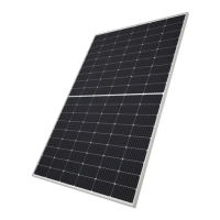
This document is an installation manual for a Crystalline Photovoltaic Module, specifically the SHARP model NU-JC415. It provides essential information for the electrical and mechanical installation, as well as safety guidelines for handling and maintaining the PV modules.
The SHARP NU-JC415 is a Crystalline Photovoltaic Module designed to convert sunlight into electricity. These modules can be wired in series to increase voltage or in parallel to increase current, forming a larger PV system. They are equipped with permanently attached junction boxes that facilitate various wiring applications. The modules are designed to operate effectively in an environmental temperature range of -40 °C to +40 °C and up to 100% relative humidity, and at altitudes up to 2,000 m. They are classified as "Class II" for protection against electric shock and rated as "Fire safety class C."
Installation: The installation of these PV modules requires a high degree of skill and should only be performed by qualified, licensed professionals. Before installation, it is crucial to consult local codes and laws for required permits and regulations. The modules should be installed and maintained by qualified personnel, with access to the installation site restricted to installer/servicer personnel.
For optimal performance, PV modules should be installed in a location free from shading throughout the year. In the Northern Hemisphere, modules typically face south, and in the Southern Hemisphere, they typically face north. The tilt angle, measured between the PV module and a horizontal ground surface, is critical for maximizing output power. For standalone systems with a battery, the tilt angle should be chosen to optimize performance when sunlight is scarcest. For grid-connected installations, tilting the module at an angle equal to the latitude of the installation site is recommended for optimum power generation throughout the year. A tilt angle of 5 degrees or more is recommended for maintenance purposes.
The modules can be mounted using clamps or bolts. When using clamps, they must meet specified dimensions and hold the module frame completely within its width. The clamp center position is critical to prevent serious deflection and cell cracks. When mounting with bolts, four M8 bolts are recommended, with a torque of 12.5 Nm. The mounting method must ensure the PV module is fixed rigidly without damage to the module or the mounting structure. The support structure must be rigid, allowing the PV module to deflect freely under wind and/or snow load without direct impact to the center of the module.
Wiring and Grounding: Correct cable connection polarity is essential for proper system operation and to maintain the warranty. PV modules can be connected in series (positive to negative) to increase voltage or in parallel (positive to positive) to increase current. Bypass diodes are built into the junction box. For parallel connections, specific options involving diodes or fuses per string are outlined to protect against reverse current overloads. The frame grounding must comply with local requirements and regulations. An example connection using a bolt, nut, and washer is provided, ensuring electrical contact with the frame. The ground wire must also meet local requirements.
Safety Precautions during Use:
The PV modules are designed for a long life and require very little maintenance.
| Type | Inverter Microwave Oven |
|---|---|
| Turntable | Yes |
| Turntable Diameter | 315 mm |
| Voltage | 230 V |
| Frequency | 50 Hz |
| Oven Type | Microwave |
| Power Output | 1000 Watts |
| Control Type | Touch |