EasyManua.ls Logo

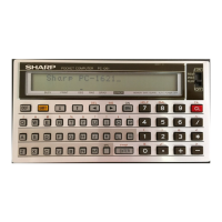
Sharp PC-E500

Sharp PC-E500
16 pages
To Next Page IconTo Next Page
Loading...
SHARP
1.
Product
outline
The
PC-E500
employs
the
large
display
(40
digits
x
4
lines)
and
32KB
memory
(standard).
2.
Specifications
Model
name
Display
Calculation
digit
Calculation
system
Program
language
CPU.
System
ROM
Memory
capacity
Stack
Basic
calculation
functions
:
PC-E500
:
:
40
digits
x
4
lines
(5
x
7
dot
matrix
liquid
crys-
tal
display)
:
Single
accuracy
calculation;
10
digits
(Mantis-
sa)
+
2
digits
(Exponent)
Double
accuracy
calculation;
20
digits
(Man-
tissa)
+
2
digits
(Exponent)
In
CAL,
MATRIX,
or
STAT
mode,
calculation
is
performed
in
single
accuracy.
:
In
theysequence
of
formula.
(Priority
judge-
ment
function)
:
BASIC
:
CMOS
8
bit
CPU
:
128K
Byte
:
System
area
about
3.8
K
Byte
Fixed
variable
(A
~
Z)
area
312
Byte
Program
data
area
28600
Byte
:
Total
145
Byte
Subroutine;
4
Byte
for
one
stage
FOR-NEXT;
21
Byte
for
one
stage
:
Basic
calculations;
Addition,
subtraction,
multiplication,
division
Functional
calculation;
Trigonometric
function,
reverse
trigonometric
function,
hyperbolic
function,
reverse
hyper-
bolic
function,
logarithm,
exponent,
angle
conversion,
power,
power
root,
coordinate
conversion,
extraction
of
the
square
root,
in-
tegration,
absolute
value,
code
function,
pi,
etc.
SHARP
CORPORATION
PC-E500
SERVICE
MANUAL
CODE:00ZPCE500SM/E
mopEL
PC-E500
Edit
function
Serial
1/0
machine
Communication
system
Communication
speed
Parity
bit
Word
length
Stop
bit
Connector
Output
signal
level
Interface
signal
Memory
protection
Operating
temperature
Power
source
Battery
operating
time
Power
consumption
External
dimension
_
Weight
Accessories
:
Cursor
shift,
right/eft
(4,
>)
Insertion
(INS)
Delete
(DEL,
BS)
Line
up,
down
(T,
4)
:
Start-stop
synchronous
(asynchronous).
sys-
tem,
half
duplex/total
duplex
mode
:
300, 600,
1200,
2400,
4800,
9600bps
(bit
per
second)
:
Even
number,
odd
number,
none
:
7,
8
bit
:
1,2
bit
:
15-pin
connector
(for
connection
with
external
devices)
:
C-MOS
level
(4
-
6V)
:
Input
......
RD,
CS,
CD
Output
......
SD,
RS, RR,
ER
Others
......
SG,
FG,
VC
:
Battery
backup
(Backups
the
program
and
data
when
the
power
is
turned
off.)
>
0~40°C
:
DC
6V
(ROS
x
4)
:
About
70
hours
of
continuous
operation
(Under
the
operating
temperature
of
20°C,
10
minutes
of
calculation
or
program
execution
and
50
minutes
of
display
for
every
hour).
,
+
There
may
be
some
variation
depending
on
the
operating
environment
and
using
condi-
tions.
:
0.07W
:
200mm
(W)
x
100mm
(D)
x
14mm
(H)
:
250g
(Including
the
battery)
:
Hard
cover,
RO3
battery
x
4,
Instruction
Manual
This
document
has
been
published
to
be
used
for
after
sales
service
only.
The
contents
are
subject
to
change
without
notice.

Other manuals for Sharp PC-E500

Question and Answer IconNeed help?

Do you have a question about the Sharp PC-E500 and is the answer not in the manual?

Sharp PC-E500 Specifications

General IconGeneral
RAM8 KB
DisplayLCD
Display Lines4
Programming LanguageBASIC
Release Year1987

Summary

Technical Specifications

Model Name

Identifies the specific model of the pocket computer.

Calculation Precision

Specifies the precision for single and double accuracy calculations.

System Block Diagram

Memory Map Configuration

LSI Description and Terminals

CPU Terminal Signal Descriptions

Details the signals and functions of the SC62015 CPU terminals.

Low Battery Detection Circuit

Servicing Notes and Procedures

Main PWB Replacement

Steps for replacing the main Printed Wiring Board.

Memory Backup Battery Replacement

Procedure for replacing the memory backup battery.

Software Diagnostic Checks

Display Check

Verifies the liquid crystal display functionality.

Mask ROM Verification

Checks the integrity and content of the Mask ROM.

Built-in RAM Check

Tests the read/write functionality of the internal RAM.

11-Pin IO Check

Verifies the functionality of the 11-pin connector I/O.

15-Pin IO Check

Verifies the functionality of the 15-pin connector I/O.

RAM Card Check

Tests the read/write functionality of the RAM card.

Error Code Descriptions

Explains error codes generated during software diagnostic checks.

Software Check Procedures

Provides specific code sequences for software verification.

Circuit Diagram

LCD Wiring Diagram

Parts Signal Arrangement

Parts Side Layout

Illustrates the arrangement of components on the device's parts side.

Parts List and Guide

Key Side Layout

Illustrates the arrangement of components on the device's key side.

Exterior Parts List

Lists external components and their part codes.

PWB Unit Parts List

Lists components and parts related to the Printed Wiring Board.

Technical Report: Mask ROM Change

Parts Change Details

Details the specific parts changed, including current and new part numbers.

Parts Interchangeability Rules

Defines rules for using current vs. new part types.

Related product manuals