18
R-120DB
R-120DK
R-120DR
R-120DW
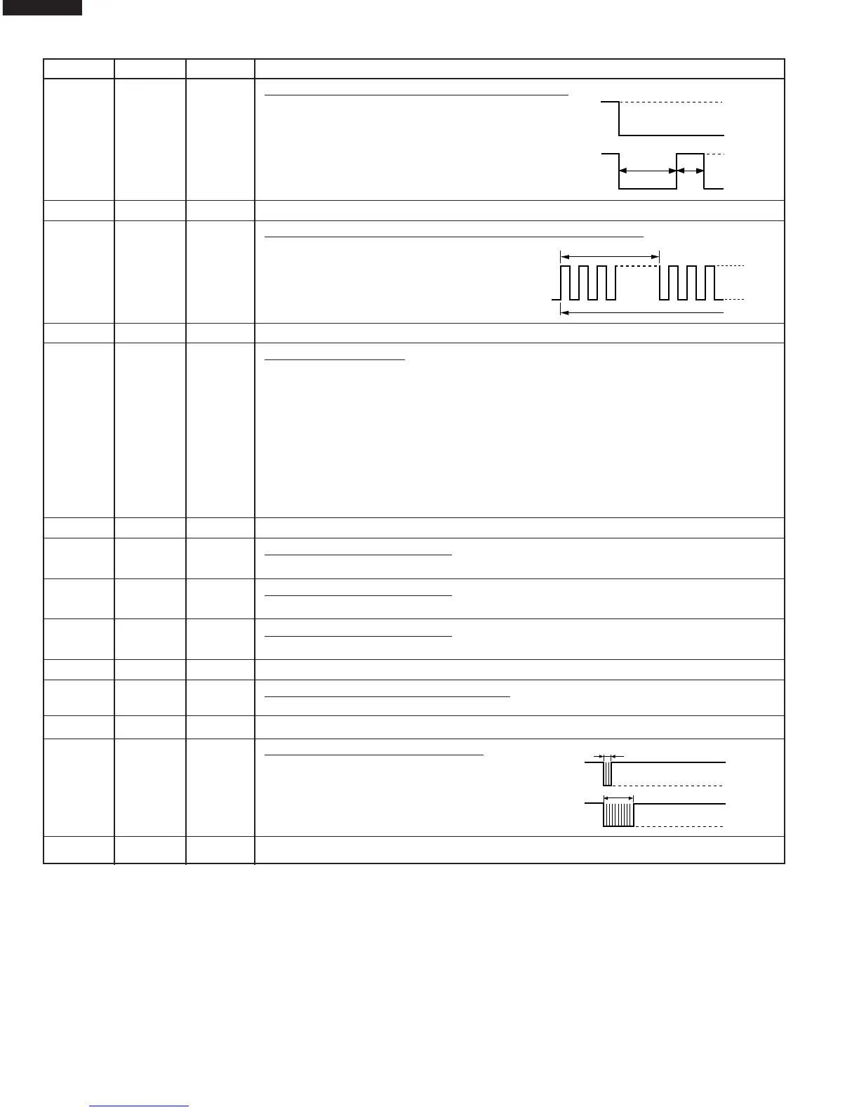
26-27 P16-17 OUT Magnetron high-voltage circuit driving signal.
To turn on and off the cook relay (RY2).
The signals holds "L" level during micro-
wave cooking and "H" level while not
cooking.
28-34 P50-P56 IN/OUT Terminal not used.
35 P57 OUT Oven lamp, fan motor and turntable motor driving signal.
To turn on and off shut off relay (RY1).
The square waveform voltage is deliv-
ered to the RY1 driving circuit and RY2
control circuit.
36-39 SEG15-SEG12 IN/OUT Terminal not used.
40-51 SEG0-SEG11 OUT Segment data signal.
Connected to LCD.
The relation between signals are as follows:
LSI signal (Pin No.) LCD (Pin No.) LSI signal (Pin No.) LCD (Pin No.)
SEG 0 (51) .............................. S1 SEG 6 (45)............................... S7
SEG 1 (50) .............................. S2 SEG 7 (44)............................... S8
SEG 2 (49) .............................. S3 SEG 8 (43)............................... S9
SEG 3 (48) .............................. S4 SEG 9 (42)............................. S10
SEG 4 (47) .............................. S5 SEG 10 (41)........................... S11
SEG 5 (46) .............................. S6 SEG 11 (40)........................... S12
52 COM3 OUT Terminal not used.
53 COM2 OUT Common data signal:COM1.
Connected to LCD (Pin No. C3)
54 COM1 OUT Common data signal:COM2.
Connected to LCD (Pin No. C2)
55 COM0 OUT Common data signal:COM1.
Connected to LCD (Pin No. C1)
56 V3 IN Connected to GND.
57-58 V1,V2 IN Power source voltage input terminal.
Standard voltage for LCD.
59-60 C1-C0 IN/OUT Terminal not used.
61 P30 OUT Signal to sound buzzer (2.0 kHz).
A: tact switch touch sound.
B: Completion sound.
62-64 P31-P33 IN/OUT Terminal not used.
Pin No. Signal I/O Description
P-HI
H : GND
L : -5V
H : GND
L : -5V
P-70
ON
ON
OFF
OFF OFF
24 sec.
8 sec.