14
R-15AM
N
PROCEDURES TO BE TAKEN WHEN THE FOIL PATTERN ON THE PRINTED WIRING BOARD
(PWB) IS OPEN
TEST PROCEDURES
PROCEDURE
LETTER COMPONENT TEST
g) The figure of all digits flicker.
h) When touching a tact switch, the control unit does not respond.
4. Other possible problems caused by defective control unit.
a) Buzzer does not sound or continues to sound.
b) Cooking is not possible.
1. Disconnect the oven from the power supply.
2. Discharge the high voltage capacitor.
3. Remove the control unit from the control panel.
4. By using an ohmmeter, check the tact switch operation.
5. When the tact switch is not depressed, an ohmmeter should indicate an open circuit. When the tact
switch is depressed, an ohmmeter should indicate a short circuit. If improper operation is indicated,
the tact switch is probably defective and should be checked.
L TACT SWITCH TEST
M RELAY TEST
To protect the electronic circuits, this model is provided with a fine foil pattern added to the primary on
the PWB, this foil pattern acts as a fuse. If the foil pattern is open, follow the troubleshooting guide given
below for repair.
Problem: POWER ON, indicator does not light up.
CARRY OUT 3D CHECKS.
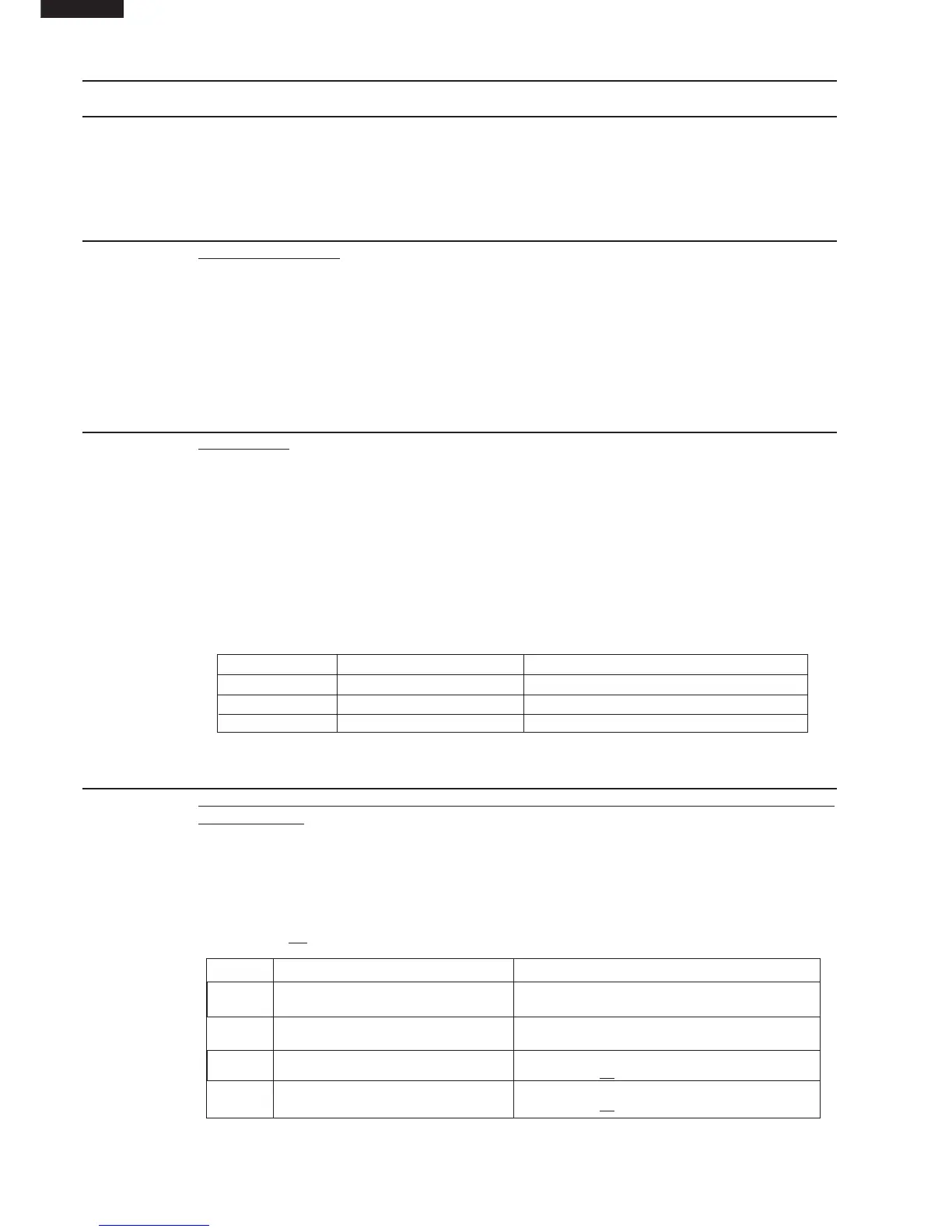
STEPS OCCURRENCE CAUSE OR CORRECTION
1
The rated AC voltage is not present at
Check supply voltage and oven power cord.
Power terminal of CPU connector (CN-A).
2
The rated AC voltage is present at primary Low voltage transformer or secondary circuit defective.
side of low voltage transformer. Check and repair.
3 Only pattern at "a" is broken.
*Insert jumper wire J1 and solder.
(CARRY OUT 3D CHECKS BEFORE REPAIR)
4 Pattern at "a" and "b" are broken.
*Insert the coil RCILF2003YAZZ between "c" and "d".
(CARRY OUT 3D CHECKS BEFORE REPAIR)
Remove the outer case and check voltage between Pin No. 1 and Pin No. 3 of the 3 pin connector (A)
on the control unit with an A.C. voltmeter.
The meter should indicate rated voltage, if not check oven circuit.
RY1, RY2 and RY3 Relay Test
These relays are operated by D.C. voltage
Check voltage at the relay coil with a D.C. voltmeter during the microwave cooking operation.
DC. voltage indicated .......... Defective relay.
DC. voltage not indicated .... Check diode which is connected to the relay coil. If diode is good,
control unit is defective.
RELAY SYMBOL OPERATIONAL VOLTAGE CONNECTED COMPONENTS
RY1 Approx. 24.0V D.C. Oven lamp / Turntable motor / Cooling fan motor
RY2 Approx. 18.0V D.C. High voltage transformer (COM.)
RY3 Approx. 18.0V D.C. High voltage transformer