12
R-15AT
TEST PROCEDURES
PROCEDURE
LETTER COMPONENT TEST
E SWITCH TEST
CARRY OUT 3D CHECKS.
Isolate the switch to be tested and using an ohmmeter check between the terminals as described in
the following table.
If incorrect readings are obtained, make the necessary switch adjustment or replace the switch.
CARRY OUT 4R CHECKS.
F THERMAL CUT-OUT TEST
CARRY OUT 3D CHECKS.
Disconnect the leads from the terminals of the thermal cut-out. Then using an ohmmeter, make a continuity
test across the two terminals as described in the below.
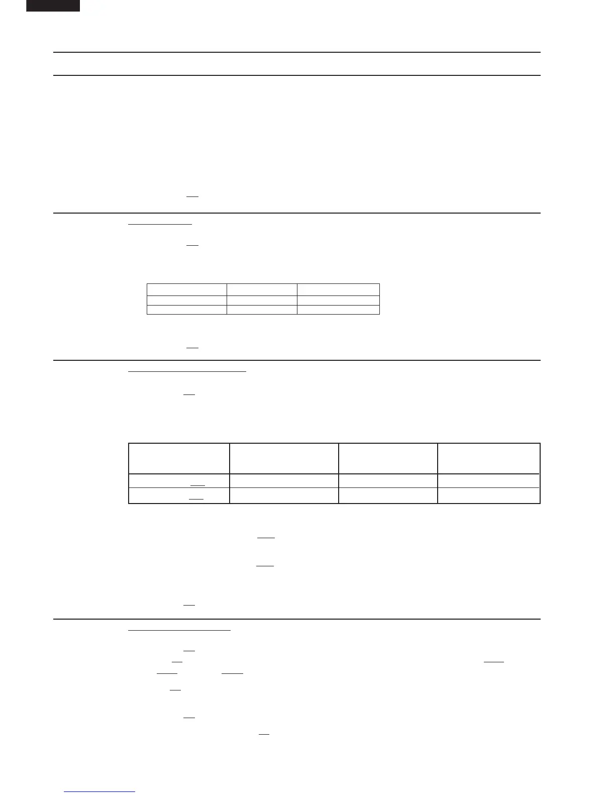
Table: Thermal Cut-out Test
Temperature of "ON" Temperature of "OFF" Indication of ohmmeter
Parts Name condition (closed circuit). condition (open circuit). (When room temperature
(˚C) (˚C) is approx. 20˚C.)
Thermal cut-out TC1125˚C
This is not resetable type. Above 125˚C Closed circuit
Thermal cut-out TC2 145˚C
This is not resetable type. Above 145˚C Closed circuit
If incorrect readings are obtained, replace the thermal cut-out.
An open circuit thermal cut-out TC2 (MG) indicates that the magnetron has overheated, this may be
due to resistricted ventilation, cooling fan failure or a fault condition within the magnetron or HV. circuit.
An open circuit thermal cut-out TC1 (OVEN) indicates that the food in the oven cavity may catch fire,
this may be due to over heating produced by improper setting of the cooking timer or failure of the
control panel.
CARRY OUT 4R CHECKS.
G BLOWN FUSE F1 F10A
CARRY OUT 3D CHECKS.
If the fuse F1 F10A is blown when the door is opened, check the 2nd. interlock switch SW2, monitor
switch SW3 and relay RY-3.
If the fuse F1 F10A is blown, there could be a short or ground in electrical parts or wire harness. Check
them and replace the defective parts or repair the wire harness.
CARRY OUT 4R CHECKS.
CAUTION: Only replace fuse
F1 F10A with the correct value replacement.
C. A normal capacitor shows continuity for a short time (kick) and then a resistance of about 10MΩ
after it has been charged.
D. A short-circuited capacitor shows continuity all the time.
E. An open capacitor constantly shows a resistance about 10 MΩ because of its internal 10MΩ
resistance.
F. When the internal wire is opened in the high voltage capacitor shows an infinite resistance.
G. The resistance across all the terminals and the chassis must be infinite when the capacitor is
normal.
If incorrect reading are obtained, the high voltage capacitor must be replaced.
CARRY OUT 4R CHECKS.
Table: Terminal Connection of Switch
Plunger Operation COM to NO COM to NC
Released Open circuit Short circuit
Depressed Short circuit Open circuit
COM; Common terminal,
NO; Normally open terminal
NC; Normally close terminal