1
R-1880LS/LST
Note: R-1880LST is the same as the R-1880LS, only the packing is different.
It is shipped on pallets for Recreational Vehicle distributors.
SERVICE MANUAL
In the interest of user-safety, the oven should be restored to its original condition and only parts identical to those specifi ed should be
used.
WARNING TO SERVICE PERSONNEL: Microwave ovens contain circuitry capable of producing very high voltage and current,
contact with following parts may result in a severe, possibly fatal, electrical shock. (High Voltage Capacitor, High Voltage Power
Transformer, Magnetron, High Voltage Rectifi er Assembly, High Voltage Harness etc..)
S66M263R1880L
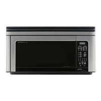
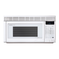
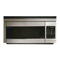
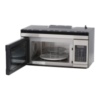
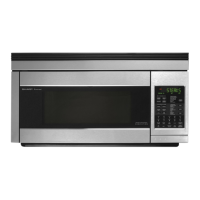
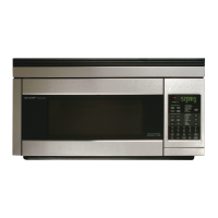
OVER THE RANGE
MICROWAVE OVEN
MODEL R-1880LS/LST
TABLE OF CONTENTS
Page
PRECAUTIONS TO BE OBSERVED BEFORE AND DURING SERVICING TO
AVOID POSSIBLE EXPOSURE TO EXCESSIVE MICROWAVE ENERGY .......................................................................2
BEFORE SERVICING...............................................................................................................................................................2
MICROWAVE MEASUREMENT PROCEDURE ....................................................................................................................4
WARNING TO SERVICE PERSONNEL .................................................................................................................................6
FOREWORD AND WARNING ................................................................................................................................................7
PRODUCT SPECIFICATIONS .................................................................................................................................................8
GENERAL INFORMATION ....................................................................................................................................................8
OPERATION ............................................................................................................................................................................11
TROUBLESHOOTING GUIDE ..............................................................................................................................................19
TEST PROCEDURE ................................................................................................................................................................22
TOUCH CONTROL PANEL ASSEMBLY .............................................................................................................................33
COMPONENT REPLACEMENT AND ADJUSTMENT PROCEDURE ..............................................................................40
PICTORIAL DIAGRAM .........................................................................................................................................................49
LSI UNIT CIRCUIT ................................................................................................................................................................50
PRINTED WIRING BOARD ..................................................................................................................................................51
PARTS LIST ............................................................................................................................................................................52
PACKING AND ACCESSORIES ............................................................................................................................................57
This document has been published to be used for after sales service only. The contents are subject to change without notice.
SHARP ELECTRONICS CORPORATION
Service Headquarters: Sharp Plaza, Mahwah, New Jersey, 07430-2135
C O N V E C T I O N M i c r o w a v e
CONVECTION
START
MICROWAVE
Convec
Low Mix
Bake
Broil
Bake
Sensor
Cook
Roast
Broil
100°F 150°F 275°F 300°F 325°F
350°F 375°F 400°F 425°F 450°F
Clock
Turntable
On/Off
Custom
Help
Kitchen
Timer
Fan
Hi/Lo
Light
Hi/Lo
Stop
Clear
Touch On
Slow
Cook
High Mix
Roast
Preheat
Sensor
Popcorn
Minute
Plus
Power
Level
Keep
Warm
Sensor
Reheat
Defrost
1 2 3 4 5
6 7
8
9 0
1 Cake
2 Brownies
3 Muffins
4 Pizza
1 Baked Potatoes
2 Frozen Veg.
3 Fresh Veg. - soft
4 Fresh Veg. - hard
5 Frozen Entrees
6 Hot Dogs
7 Bacon
8 Fish, Seafood
1 Poultry
2 Chicken Pieces
3 Turkey Breast
4 Pork Loin
1 Hamburgers
2 Chicken Breast
3 Steaks
4 Pork Chops
SHARP CORPORATION
SHARP ELECTRONICS OF CANADA LTD.
Head Offi ce: 335 Britannia Road East, Mississauga, Ontario L4Z 1W9
(905) 890-2100
(IN USA):
(IN CANADA):