18
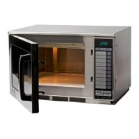
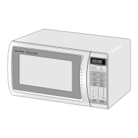
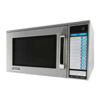
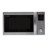
R-22AT
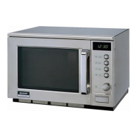
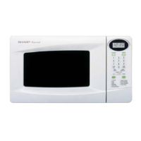
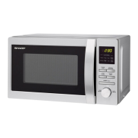
R-23AM
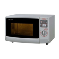
R-24AT
CONTROL PANEL ASSEMBLY FOR R-23AM
OUTLINE OF CONTROL PANEL
The control section consists of the following units as
shown in the control panel circuit.
(1) Control Unit
(2) Switch Unit
(3) Encoder Unit
The principal functions of these units and the signals commu-
nicated among them are explained below.
1. Control Unit
Signal of switch touch and oven function control are all
processed by one microcomputer.
1) Power Supply Circuit
This circuit changes output voltage at the secondary
side of the low voltage (T1) transformer to volatges
required at each part by full wave rectifying circuit,
constant voltage circuit, etc..
2) ACL Circuit
This is an Auto-clear Circuit, i.e., a reset circuit, which
enables IC1 to be activated from initial state.
3) Power Synchronizing Signal Generating Circuit
This is a circuit for generating power synchronizing
signal by virtue of the secondary side output of trans-
former T1.
This signal is used for a basic frequency to time
processing and so on.
4) Clock Circuit
This is a circuit for controlling clock frequency required
for operating IC1.
5) IC1 (Main Processor)
This is a one-chip microcomputer, responsible for
controlling the entire control unit.
6) Display Circuit
This is a circuit for driving display tubes by IC1 output.
7) Switch Input Circuit
This is a circuit for transmitting switch input information
to IC1.
8) Sound-body Driving Circuit
This is a circuit for driving sound body by IC1 output.
9) Relay Driving Circuit
This is a circuit for driving output relay by IC1 output.
10) Stop Switch Circuit
This is a circuit for driving IC1 to detect door opening/
closing.
11) Exhaust Air Temperature Detecting Circuit
This is a circuit for transmitting output change of
thermistor (Oven thermistor (1)) to IC1.
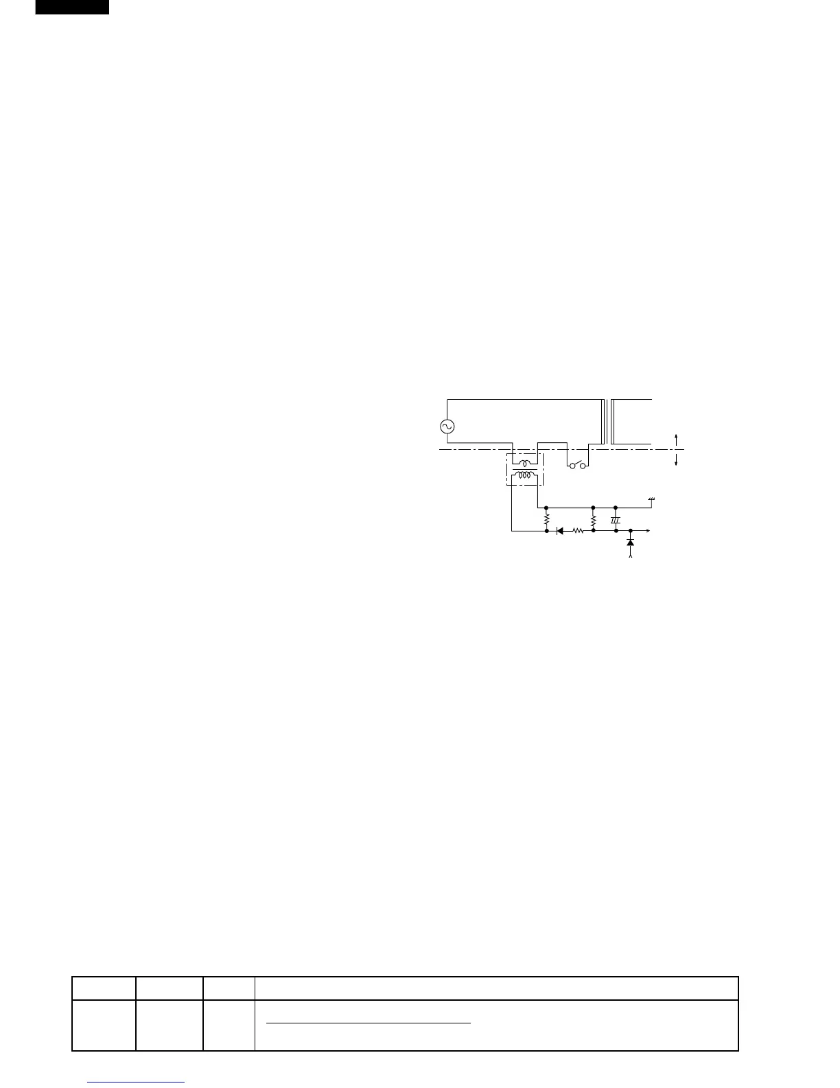
12) High Voltage Monitoring Circuit.
This circuit detects problems in the magnetron / high
voltage circuit by sensing a variation in the current
flowing through the primary winding of the high voltage
transformer. During heating, the primary current of the
high voltage transformers also flows through the pri-
mary winding of the current transformers CT1 and
CT2. This causes a current to be induced in the
secondary windings of CT1/CT2 and results in an AC
voltage which is determined by R30/R31. This AC
voltage is then half wave rectified by D30/D31 and
smoothed (filtered) by C30/C31. This AC voltage is the
input to the AN3 and AN4 ports of IC1, which deter-
mines if there is a magnetron / high voltage problem.
Figure T-1. High Voltage Monitoring Circuit For R-23AM
13) Magnetron Temperature Detecting Circuit.
This is a circuit for transmitting output change of
thermistor (Magnetron thermistor) to IC1.
14) Oven Cavity Temperature Detecting Circuit.
This is a circuit for transmitting output change of
thermistor (Oven thermistor (2)) to IC1.
2. Switch Unit
The switch unit is composed of a matrix circuit in which
when a switch it touched, one of signals P43 - P45
generated by the LSI, is passed through the switch and
returned to the LSI as one of signals P50 - P51.
3. Encoder
The encoder converts the signal generated by LSI into
the pulse signal, and the pulse signal is returned to the
LSI.
HIGH VOLTAGE TRANSFORMER
HIGH VOLTAGE CIRCUIT
MAIN BODY SIDE
T/C SIDE
CT1 or CT2
RY2 or RY3
R30 or
R31
R34 or
R35
D30 or
D31
R32 or
R33
Vc
C30 or C31
IC1
AN3 or
AN4 PORT
D32 or
D33
DESCRIPTION OF LSI FOR R-24AT / R-22AT
LSI(IZA646DR)
The I/O signal of the LSI(IZA646DR) is detailed in the following table.
Pin No. Signal I/O Description
1 VREF IN Reference voltage input terminal.
A reference voltage applied to the A/D converter in the LSI. Connected to GND.(0V)