21
R-22AT
R-23AM
R-24AT
45 P11 OUT Segment data signal. Signal similar to P17.
Key strobe signal.
Signal applied to touch-key section. A pulse signal is input to R0 - R3 terminal while
one of G-7 line keys on key matrix is touched.
46 P10 OUT Segment data signal. Signal similar to P17.
47-48 P07-P06 OUT Segment data signal. Signal similar to P17.
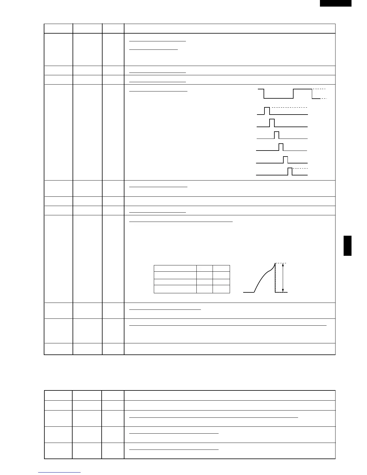
49 P05 OUT Digit selection signal.
The relation between digit signal and digit
are as follows:
Digit signal Digit
P05.................... 1st.
P04................... 2nd.
P03....................3rd.
P02.................... 4th.
P01.................... 5th.
P00.................... 6th.
Normally, one pulse is output in every ß
period, and input to the grid of the Fluores-
cent Display.
50-54 P04-P00 OUT Digit selection signal.
Signal similar to P16.
55-57 P27-P25 OUT Terminal not used.
58-59 P24-P23 OUT Segment data signal. Signal similar to P17.
60 P22 OUT (Sound) Voltage level control terminal.
This terminal (P22) is to control volume level of buzzer sound with terminals P21.
Since the volume level of buzzer sound depends on voltage energized, it is control
level in 3 steps by combining signal levels for P22, P21. Relationship of signal level
combination to sound volume level is shown in the following table, 1~3 in the table,
however, are indicated in the descending order from the maximum level of sound
volume through the minimum level.
Sound Volume P21 P22
1, (Max.) L L
2, H L
3, (Min.) L H
*At Output terminal P32, rectangular wave signal of 2.5kHz is output.
61 P21 OUT Sound level control signal.
Refer to above signal P22.
62 P20 IN Input signal which communicates the door open/close information to LSI.
Door closed; "H" level signal(0V).
Door opened; "L" level signal(-31.0V).
63/64 AVCC/VCC IN Connected to GND.
Pin No. Signal I/O Description
H
L
GND
ß(50Hz)
P05
P04
P03
P02
P01
P00
GND
-31(V)
-31(V)
A
A : 1,(Max) 20V
2, 13V
3,(Min) 7V
DESCRIPTION OF LSI FOR R-23AM
LSI(IZA648DR)
The I/O signal of the LSI(IZA648DR) is detailed in the following table.
Pin No. Signal I/O Description
1 VCC IN Connected to GND.
2 VEE IN Anode (segment) of Fluorescent Display light-up voltage: -35V.
Vp voltage of power source circuit input.
3 AVSS IN Reference voltage input terminal.
A reference voltage applied to the A/D converter in the LSI. Connected to DC. (-5V)
4 VREF IN Reference voltage input terminal.
A reference voltage applied to the A/D converter in the LSI. Connected to GND.