31
R-22AT
R-23AM
R-24AT
TERMINAL INSULATOR REPLACEMENT
CONTROL PANEL ASSEMBLY REMOVAL
The complete control panel should be removed for re-
placement of components. To remove the control panel,
proceed as follows:
1. CARRY OUT 3D CHECKS.
2. Remove the air intake filter assembly from the base
plate.
3. Remove two (2) screws holding the control panel to the
base plate.
4. Pull down the control panel and remove it forward.
5. Disconnect two connectors (A), (B), (H) and TAB
terminal (TAB1,2,3,4) from the control unit.
6. Now the control panel assembly is free.
CAUTION FOR TOUCH CONTROL PANEL REMOVAL
1) Hold the lower end (Position A, Fig. 1) of the touch
control panel assembly firmly while sliding it down and
toward you.
DO NOT FORCE THE CONTROL UNIT TO SLIDE
DOWN DURING REMOVAL. THIS MAY CAUSE DAM-
AGE TO THE CONTROL UNIT BY HITTING A RE-
LAY (RY-4 for R-22AT/24AT ; RY-3 for R-23AM) OR
THE TAB TERMINALS LOCATED AT THE FRONT
OF THE OVEN CAVITY.
2) If the Touch Control Panel is hard to remove;
(1) Insert a flat head screw driver into space B . (Fig. 1)
(2) Rotate the screwdriver clockwise while holding posi-
tion C of the Touch Control Panel. (Fig. 2)
TO AVOID DAMAGE TO TOUCH CONTROL PANEL,
COVER THE TIP OF SCREWDRIVER WITH TAPE.
(3) If the relay (RY-4 for R-22AT/24AT ; RY-3 for R-23AM)
is hit, re-solder the Relay (RY-4) prior to reinstalling the
Touch Control Panel.
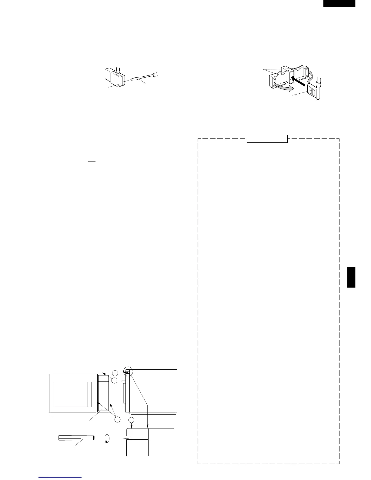
1. Open covers of the terminal insulator by using small flat
type screw driver.
2. Remove the receptacle from the terminal insulator.
3. Now, the terminal insulator is free.
CONTROL PANEL ASSEMBLY AND CONTROL UNIT REMOVAL
Installation
1. Insert the receptacle into terminal insulator.
2. Close covers of the terminal insulator, as shown
illustlated below.
B
A
C
B
Fig. 1
Fig. 2
TOUCH CONTROL PANEL
SCREW DRIVER
Flat type
screw driver
Terminal
insulator
RECEPTACLE
COVERS
Replacement of individual component is as follows:
for R-23AM
CONTROL UNIT AND CONTROL PANEL FRAME
(WITH SWITCH UNIT)
7. Remove two (2) screws holding the control panel
mounting angle to the panel frame.
8. Lift up the control panel mounting angle from the
panel frame.
9. Disconnect the connectors (J) and (E) from the
control unit.
10.Remove six (6) screws holding the control unit to the
panel frame assembly.
11.Push down the right side two (2) hooks fixing the
control unit to the panel frame assembly, and lift up
the control unit upward.
12.Now, the control unit and control panel frame (with
switch unit) are free.
CAUTION:
At installing control panel unit assembly to main
body set:
1. Ensure the installation of wiring-related parts
without negligence.
2. When inserting wire cable to main body set,
ensure them free from caught-in trouble. In addi-
tion, when installing the control panel assembly
to base plate with screws, be sure of pushing the
control panel unit upward to fix with screws
firmly.
3. Do not allow any wire leads to come near the
varistor works, because it will explode and the
wire leads near by the varistor will be damaged.
SWITCH UNIT
13.Remove the three (3) screws holding the switch unit
(Main) to the control panel frame.
14.Remove the two (2) screws holding the switch unit
(Sub.) to the control panel frame.
15.Now, the switch unit is free
ROTARY ENCODER
13.Remove the one (1) screw holding the earth wire to
the rotary encoder.
14.Remove the two (2) screws and one (1) washer
holding the rotary encoder to the control panel
frame.
15.Remove the knob from the rotary encoder shaft.
16.Now, the rotary encoder is free.