22
R-330DK
R-330DW
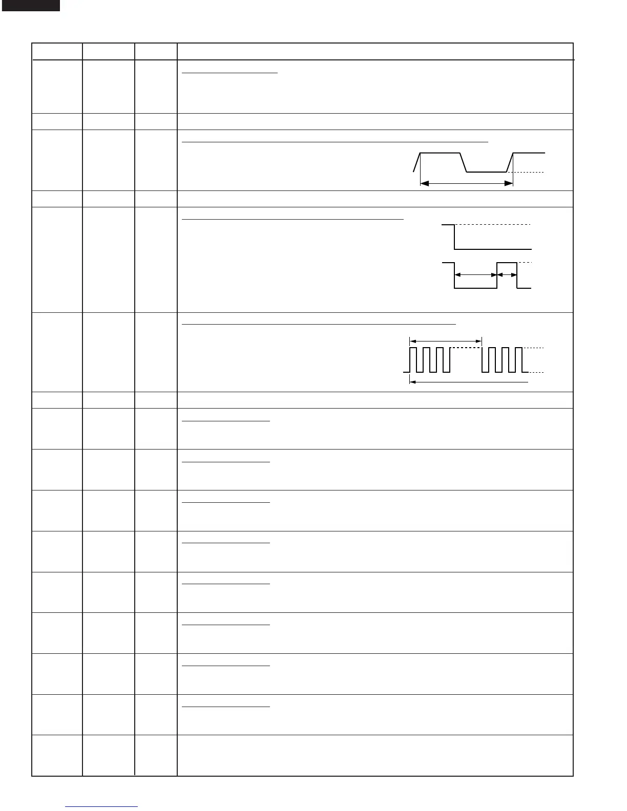
12 RESET IN Auto clear terminal.
Signal is input to reset the LSI to the initial state when power is applied. Temporarily set
"L" level the moment power is applied, at this time the LSI is reset. Thereafter set at "H"
level.
13 INTP0 IN Connected to VC.
14 INTP1 IN Signal synchronized with commercial power source frequency.
This is the basic timing for time processing of LSI.
15 P02 OUT Terminal not used.
16 P03 OUT Magnetron high-voltage circuit driving signal.
To turn on and off the cook relay (RY2). The
signals holds "L" level during microwave cook-
ing and "H" level while not cooking. In other
cooking modes (variable cooking) the signal
turns to "H" level and "L" level in repetition
according to the power level.
(ON and OFF times for other power level.)
17 P04 OUT Oven lamp, fan motor and turntable motor driving signal
To turn on and off shut off relay (RY1). The
square waveform voltage is delivered to the
RY1 driving circuit and RY2 control circuit.
18 P05 OUT Terminal not used.
19 P110 OUT Key strobe signal.
Signal applied to touch-key section. A pulse signal is input to ANI7, P100, P101, P102
and P103 terminal while one of G8 line keys on key matrix is touched.
20 P111 OUT Key strobe signal.
Signal applied to touch-key section. A pulse signal is input to ANI7, P100, P101, P102
and P103 terminal while one of G7 line keys on key matrix is touched.
21 P112 OUT Key strobe signal.
Signal applied to touch-key section. A pulse signal is input to ANI7, P100, P101, P102
and P103 terminal while one of G6 line keys on key matrix is touched.
22 P113 OUT Key strobe signal.
Signal applied to touch-key section. A pulse signal is input to ANI7, P100, P101, P102
and P103 terminal while one of G5 line keys on key matrix is touched.
23 P114 OUT Key strobe signal.
Signal applied to touch-key section. A pulse signal is input to ANI7, P100, P101, P102
and P103 terminal while one of G4 line keys on key matrix is touched.
24 P115 OUT Key strobe signal.
Signal applied to touch-key section. A pulse signal is input to ANI7, P100, P101, P102
and P103 terminal while one of G3 line keys on key matrix is touched.
25 P116 OUT Key strobe signal.
Signal applied to touch-key section. A pulse signal is input to ANI7, P100, P101, P102
and P103 terminal while one of G2 line keys on key matrix is touched.
26 P117 OUT Key strobe signal.
Signal applied to touch-key section. A pulse signal is input to ANI6, ANI7, P100, P101,
P102 and P103 terminal while one of G1 line keys on key matrix is touched.
27 AVSS IN Connected to VC.
Pin No. Signal I/O Description