R405KST
9 – 2
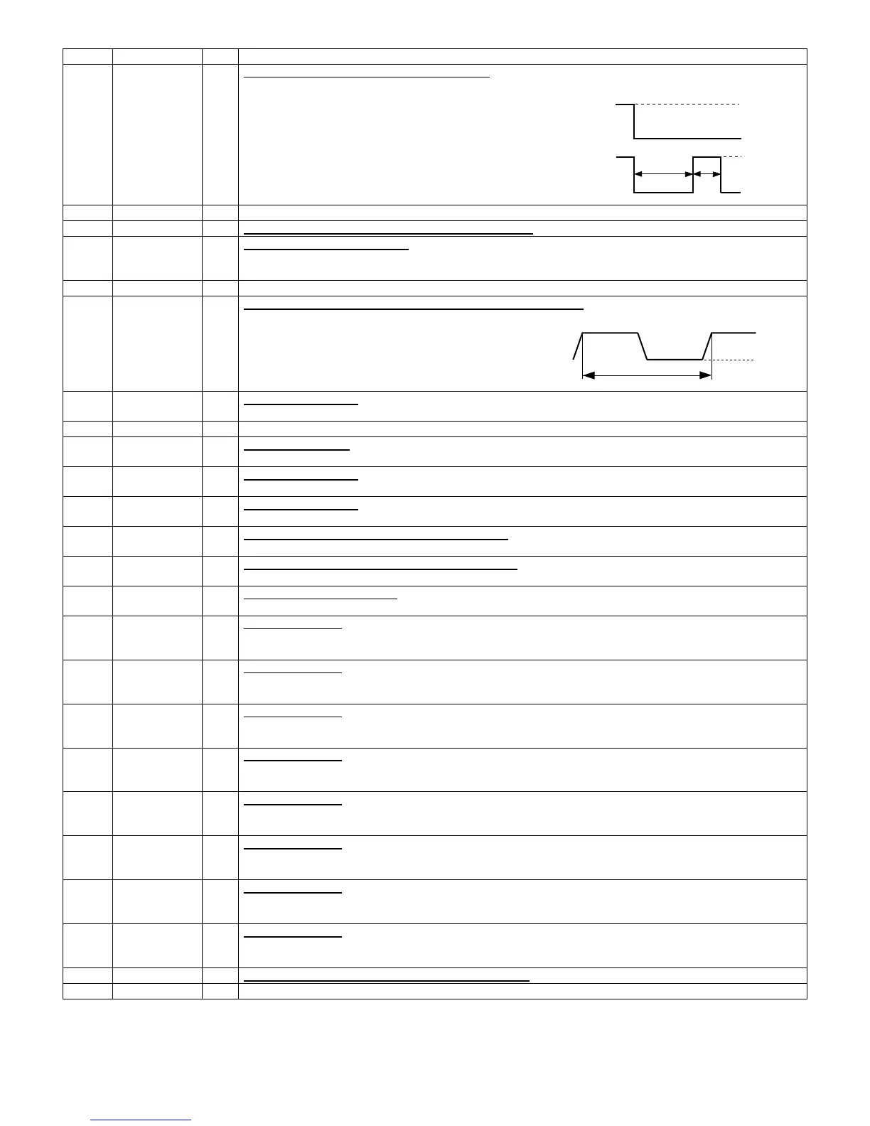
18 P50 OUT
Magnetron high-voltage circuit driving signal.
To turn on and off the cook relay (RY2). The signals
holds “L” level during microwave cooking and “H” level
while not cooking. In other cooking modes (variable
cooking) the signal turns to “H” level and “L” level in
repetition according to the power level.
19 P47 IN Connected to GND.
20 P46 OUT Night light circuit (light emitting diode) driving signal.
21 P45 IN
Signal coming from touch key.
When either G12 line on key matrix is touched, a corresponding signal out of P20 - P27 will be input into P45.
When no key is touched, the signal is held at “H” level.
22-23 P44-P43 OUT Terminal not used.
24 INTP0 IN
Signal synchronized with commercial power source frequency.
This is the basic timing for time processing of LSI.
25 P41 IN
Signal similar to P45.
When either G11 line on key matrix is touched, a corresponding signal will be input into P41.
26 P40 IN Connected to GND through the pull-down resistor.
27 RESET IN
Auto clear terminal.
Signal is input to reset the LSI to the initial state when power is applied.
28 P71 IN
Signal similar to P45.
When either G10 line on key matrix is touched, a corresponding signal will be input into P71.
29 P70 IN
Signal similar to P45.
When either G9 line on key matrix is touched, a corresponding signal will be input into P70.
30 XIN IN
Internal clock oscillation frequency input setting.
The internal clock frequency is set by inserting the ceramic filter oscillation circuit with respect to XOUT terminal.
31 XOUT OUT
Internal clock oscillation frequency control output.
Output to control oscillation input of XIN.
32 VSS IN
Power source voltage: -5.0V.
The power source voltage to the drive LSI is input to VSS terminal.
33 P27 OUT
Key strobe signal.
Signal applied to touch-key section. A pulse signal is input to P70, P71, P41 and P45 terminal while one of G8
line keys on key matrix is touched.
34 P26 OUT
Key strobe signal.
Signal applied to touch-key section. A pulse signal is input to P70, P71, P41 and P45 terminal while one of G7
line keys on key matrix is touched.
35 P25 OUT
Key strobe signal.
Signal applied to touch-key section. A pulse signal is input to P70, P71, P41 and P45 terminal while one of G6
line keys on key matrix is touched.
36 P24 OUT
Key strobe signal.
Signal applied to touch-key section. A pulse signal is input to P70, P71, P41 and P45 terminal while one of G5
line keys on key matrix is touched.
37 P23 OUT
Key strobe signal.
Signal applied to touch-key section. A pulse signal is input to P70, P71, P41 and P45 terminal while one of G4
line keys on key matrix is touched.
38 P22 OUT
Key strobe signal.
Signal applied to touch-key section. A pulse signal is input to P70, P71, P41 and P45 terminal while one of G3
line keys on key matrix is touched.
39 P21 OUT
Key strobe signal.
Signal applied to touch-key section. A pulse signal is input to P70, P71, P41 and P45 terminal while one of G2
line keys on key matrix is touched.
40 P20 OUT
Key strobe signal.
Signal applied to touch-key section. A pulse signal is input to P70, P71, P41 and P45 terminal while one of G1
line keys on key matrix is touched.
41 P17 OUT Back light signal (light emitting diode) driving signal.
42-55 P16-P3 OUT Terminal not used.
Pin No. Signal I/O Description