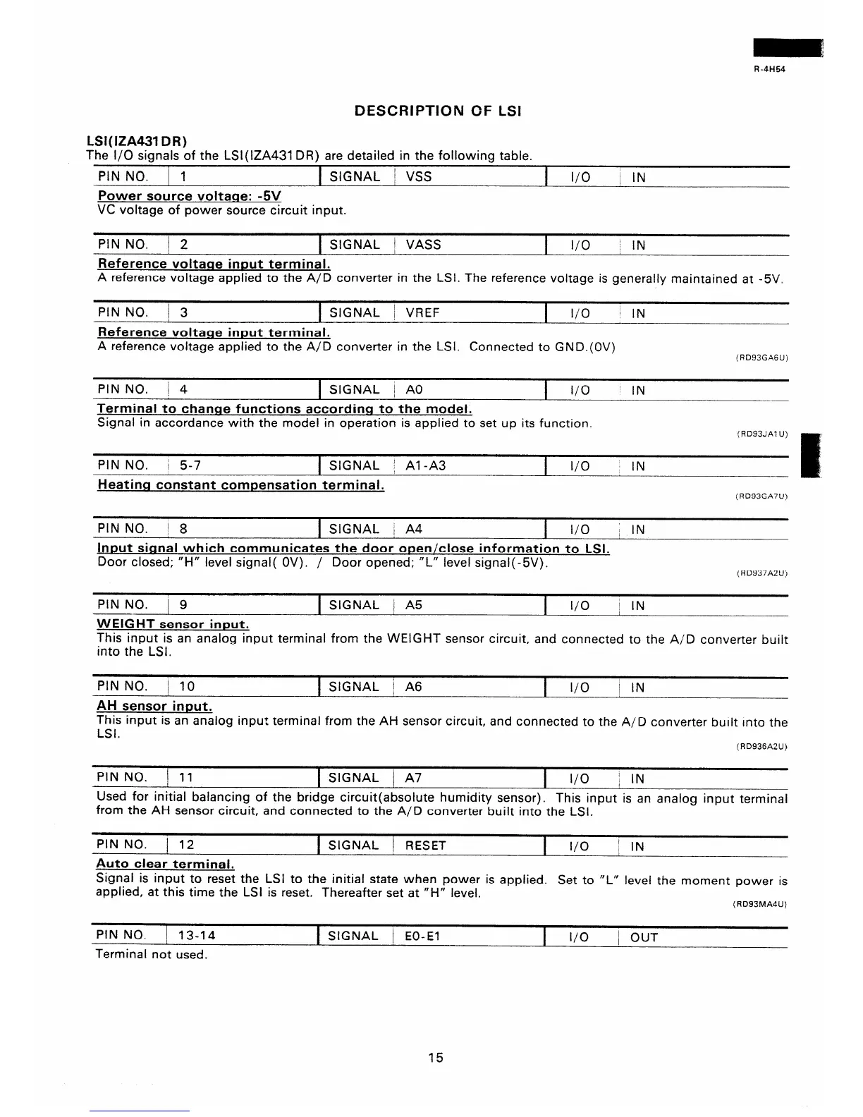
R-4H54
DESCRIPTION OF LSI
LSI( IZA431 DR)
The l/O signals of the LSl(lZA431 DR) are detailed in the following table.
PIN NO. 1 1
SIGNAL / VSS
I
I/O
i IN
Power source voltace: -5V
VC voltage of power source circuit input.
PIN NO. / 2
f SIGNAL j VASS 1 I/O j IN
Reference voltarre inDut terminal.
A reference voltage applied to the A/D converter in the LSI. The reference voltage is generally maintained at -5V.
PIN NO. ! 3
1 SIGNAL ! VREF
I
I/O
1 IN
Reference voltage input terminal.
A reference voltage applied to the A/D converter in the LSI. Connected to GND.(OV)
(RD93GA6U)
PIN NO.
j 4
1 SIGNAL 1 A0
I
I/O
Terminal to change functions according to the model.
Signal in accordance with the model in operation is applied to set up its function.
IN
(RD93JAl U)
PIN NO.
i 5-7
1 SIGNAL / Al-A3
I
I/O
IN
Heatinq constant compensation terminal.
(RD93GA7U)
PIN NO. / 8
1 SIGNAL / A4
I
I/O ~ IN
Input signal which communicates the door open/close information to LSI.
Door closed; “H” level signal( OV). / Door opened; “L” level signal( -5V).
(RD937A2Uj
PIN NO. 1 9 1 SIGNAL j A5
I
l/O
j IN
WEIGHT sensor input.
This input is an analog input terminal from the WEIGHT sensor circuit, and connected to the A/D converter built
into the LSI.
PINNO. / 10 1 SIGNAL j A6
I l/O
1 IN
AH sensor input.
This input is an analog inpu? terminal from the AH sensor circuit, and connected to the A/D converter built into the
LSI.
(RD936A2U)
PIN NO.
j 11
1 SIGNAL j A7
I
I/O
/ IN
Used for initial balancing of the bridge circuit(absolute humidity sensor). This input is an analog input terminal
from the AH sensor circuit, and connected to the A/D converter built into the LSI.
PINNO. / 12
1 SIGNAL i RESET
I
I/O
1 IN
Auto clear terminal,
Signal is input to reset the LSI to the initial state when power is applied. Set to “L” level the moment power is
applied, at this time the LSI is reset. Thereafter set at “H” level.
(RD93MA4U)
PIN NO. 1 13-14
Terminal not used.
1 SIGNAL 1 EO-El
I
I/O
/ OUT
15
 Loading...