R-4H54
PIN NO. / 28 SIGNAL i H3
I
l/O I IN
Sianal similar to HO.
When any one of G-9 line keys on key matrix is touched, a corresponding signal will be input into H3.
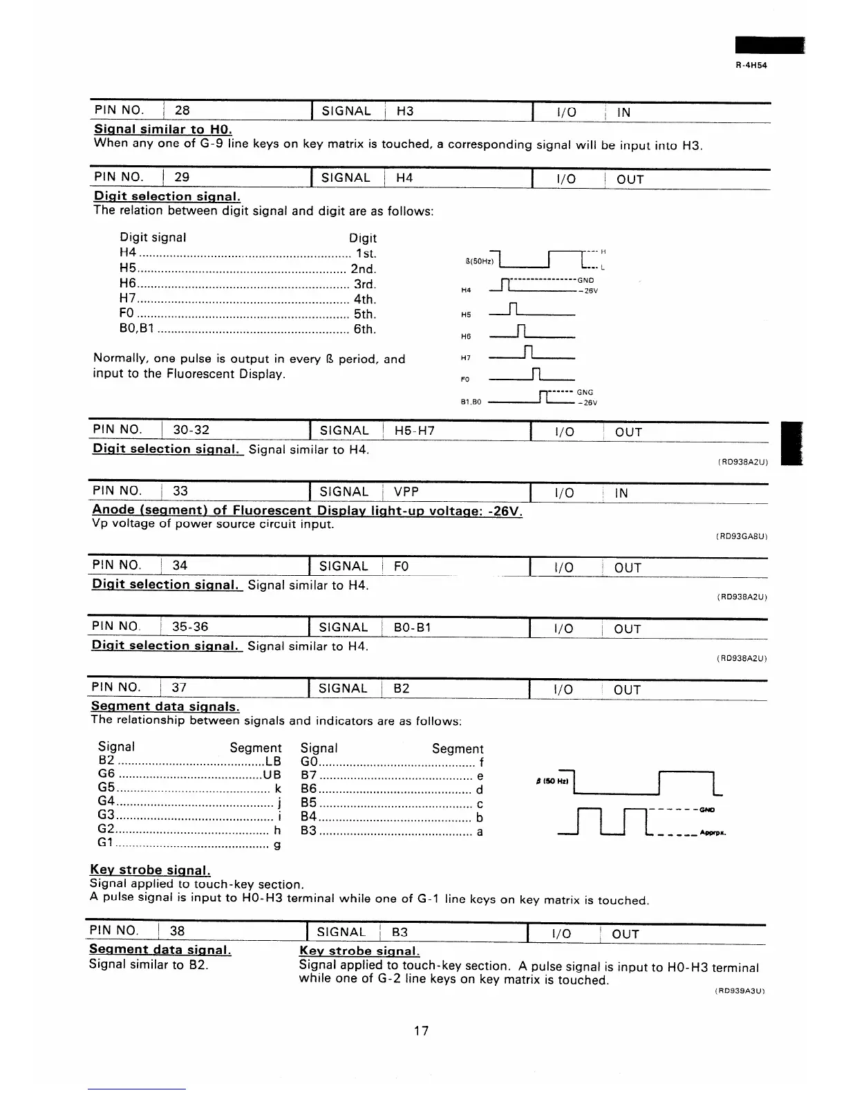
PIN NO. / 29
t SIGNAL / H4
I I/O
1 OUT
Digit selection signal.
The relation between digit signal and digit are as follows:
Digit signal
Digit
H4 . . . . . . . . . . . . . . . . . . . . . . . . . . . . . . . . . . . . . . . . . . . . . . . . . . . . . . . . . . . . . .
1 st.
H5 . . . . . . . . . . . . . . . . . . . . . . . . . . . . . . . . . . . . . . . . . . . . . . . . . . . . . . . . . . . . .
2nd.
H6 3rd.
- --------- -- --_- GND
. . . . . . . . . . . . . . . . . . . . . . . . . . . . ..*.............*.................
H4
H7
- 26V
. . . . . . . . . . . . . . . . . . . . . . . . . . . . . . . . . . . . . . . . . . . . . . . ..*............
4th.
FO
. . . . . . . . . . . . . . . . . . . . . . . . . . . . . . . . . ..*.........*.**.............
5th.
H5 n
BO,Bl
. . . . . . . . . . . . . . . . . . . . . . . . . . . . . . . . . . . . . . . . . . . . . . . . . . . . . . . .
6th.
H6 n
Normally, one pulse is output in every 13 period, and
input to the Fluorescent Display.
H7 n
FO n
Bl .BO
GNG
- 26V
PIN NO. 1 30-32 1 SIGNAL j H5-H7
Digit selection signal. Signal similar to H4.
I
I/O
j OUT
(RD938A2U)
PIN NO.
/ 33
1 SIGNAL / VPP
I
I/O
1 IN
Anode (segment) of Fluorescent Displav light-up voltaqe: -26V.
Vp voltage of power source circuit input.
(RD93GA8IJ)
PIN NO. 1 34
/
1 SIGNAL i FO
Diait selection signal. Signal similar to H4.
I
l/O
j OUT
CRD938A2U)
PIN NO.
j 35-36 1 SIGNAL / BO-Bl
I
I/O
; OUT
Dinit selection signal. Signal similar to H4.
(RD938A2U)
PIN NO.
/ 37
1 SIGNAL / 82
Segment data signals.
The relationship between signals and indicators are as follows:
I
I/O
OUT
Signal
Segment Signal
B2
Segment
. . . . . . . . . . . . . . . ..*....*.................... LB GO *.................................a........... f
EE
. . . . . . . . . . . . . . . . . . . . . . . . . . . . . . . . . . . . . . . . . . UB
B7 . . . . . . . . . . . . . . . . . . . . . . . . . . . . . . . . . . . . . . . . . . . . . e
. . . . . . . . . . . . . . . . . . . . . . . . . . . . . . . . . . . . . . . . . . . . .
k
B6 . . . . . . . . . . . . . . . . . . . . . . . . . . . . . . . . . . . . . . . . . . . . .
d
:i . . . . . . . . . . . . . . . . . . . * . . . . . . . . . . . . . . . . . . . . . . . . . .
-
. . . . . . . . . . . . . . . . . . . . . . . . . . . . . . . . . . . . . . . ...*...
!
B5 . . . . . . . . . . . . . . . . . . . . . . . . . . . . . . . . . . . . . . . . . . . . .
c
~~“““““‘.“‘.““‘.....“““.““.“““’
b
G2 . . . . . . . . . . . . . . . . . . . . . . . . . . . . . . . . . . . . . . . . . . . . . h
. . . . . . . . . . . . . . . . ..a..........................
a
Gl
. . . . . . . . . . . . . . . . . . . . . . . . . . . . . . . . . . . . . . . . . . . . .
g
Kev strobe siqnal.
Signal applied to touch-key section.
A pulse signal is input to HO-H3 terminal while one of G-l line keys on key matrix is touched.
PIN NO. 1 38
Segment data sianal.
Signal similar to 82.
1 SIGNAL / B3
I
I/O
/ OUT
Kev strobe signal.
Signal applied to touch-key section. A pulse signal is input to HO-H3 terminal
while one of G-2 line keys on key matrix is touched.
(RD939A3U)
17
 Loading...