DESCRIPTION OF LSI
LSI(IZA506DR)
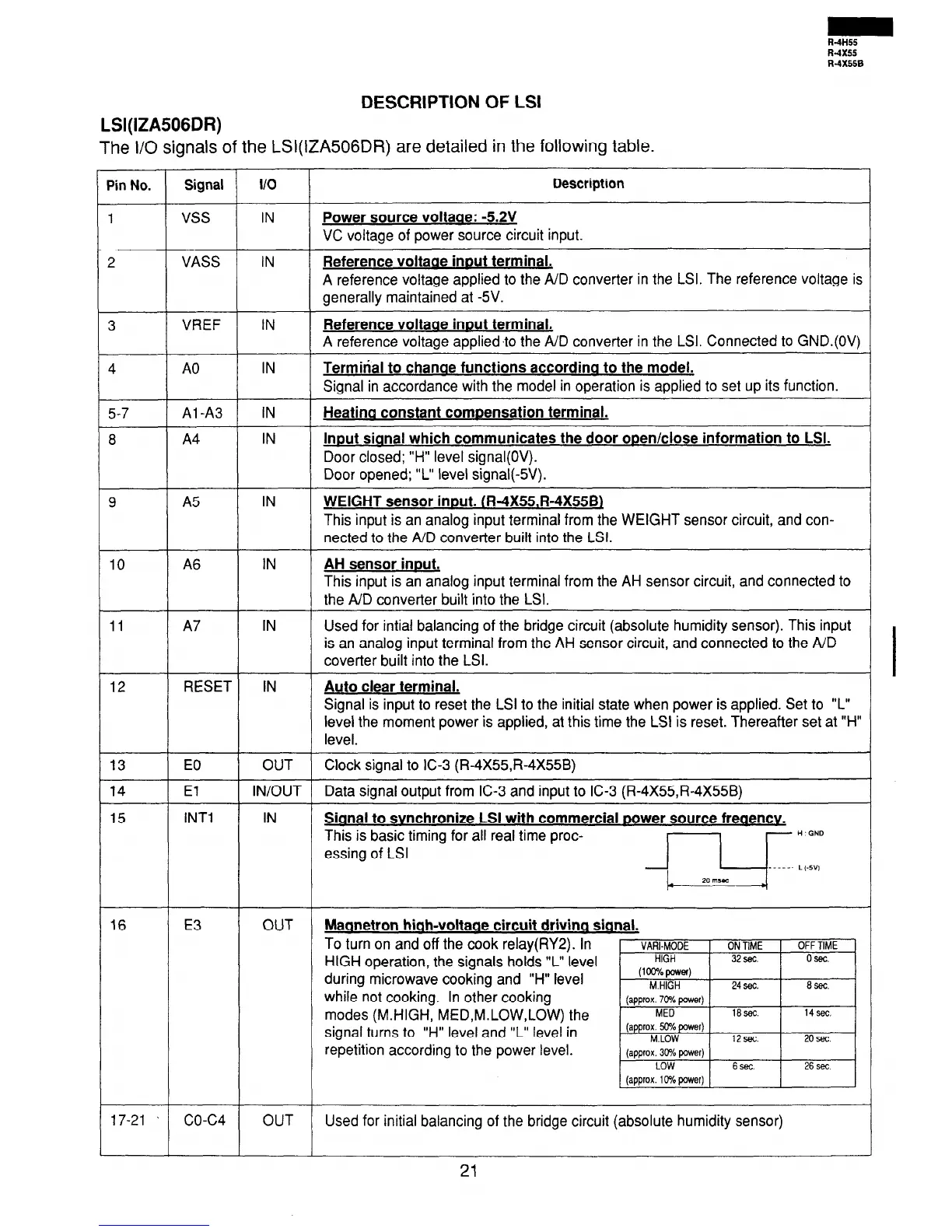
The I/O signals of the LSI(IZA506DR) are detailed in the following table.
Pin No.
Signal
110
Description
1
vss
IN
Power source voltaae: -5.2V
VC voltage of power source circuit input.
2
VASS IN
Reference voltaae inout terminal.
A reference voltage applied to the A/D converter in the LSI. The reference voltage is
generally maintained at -5V.
3
VREF IN
Reference voltaae innut terminal.
A reference voltage appliedI the A/D converter in the LSI. Connected to GND.(OV)
4
A0
IN
Terminal to chanae functions accordina to the model.
Signal in accordance with the model in operation is applied to set up its function.
5-7
Al-A3 IN
Heatina constant comnensation terminal.
8
A4
IN
Innut sianal which communicates the door ooenklose information to LSI.
Door closed; “H” level signal(
Door opened; “L” level signal(-5V).
9
A5
IN
WEIGHT sensor innut. (R-4X55.R-4X55Bl
This input is an analog input terminal from the WEIGHT sensor circuit, and con-
nected to the A/D converter built into the LSI.
10
A6
IN AH sensor innut.
This input is an analog input terminal from the AH sensor circuit, and connected to
the A/D convener built into the LSI.
11
12
13
14
15
A7
IN
Used for intial balancing of the bridge circuit (absolute humidity sensor). This input
is an analog input terminal from the AH sensor circuit, and connected to the A/D
coverter built into the LSI.
RESET IN
Auto clear terminal.
Signal is input to reset the LSI to the initial state when power is applied. Set to “L”
level the moment power is applied, at this time the LSI is reset. Thereafter set at “H”
level.
EO
OUT Clock signal to IC-3 (R-4X55,R-4X55B)
El IN/OUT Data signal output from IC-3 and input to IC-3 (R-4X%,R-4X55B)
INTl IN Sianal to svnchronize LSI with commercial Dower source freaencv.
This is basic timing for all real time proc-
essing of LSI
j--J& : 17
16 E3 OUT
Maanetron hiah-voltaae circuit drivina sianal.
To turn on and off the cook relay(RY2). In
HIGH operation, the signals holds “L” level
during microwave cooking and “H” level
while not cooking. In other cooking
modes (M.HIGH, MED,M.LOW,LOW) the
signal turns to “H” level and “L” level in
repetition according to the power level.
17-21 ~
co-c4 OUT Used for initial balancing of the bridge circuit (absolute humidity sensor)
21