R -6280
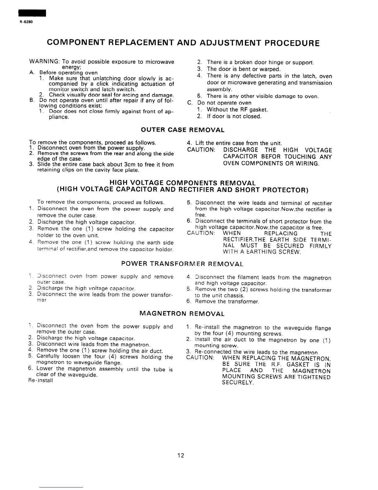
COMPONENT REPLACEMENT AND ADJUSTMENT PROCEDURE
WARNING: To avoid possible exposure to microwave 2.
A.
energy;
Before operating oven
1. Make sure that unlatching door slowly is ac-
companied by a click indicating actuation of
monitor switch and latch switch.
B.
2. Check visually door seal for arcing and damage.
Do not operate oven until after repair if any of fol-
lowing conditions exist;
1. Door does not close firmly against front of ap-
pliance.
To
::
3.
remove the components, proceed as follows. 4. Lift the entire case from the unit.
Disconnect oven from the power supply.
Remove the screws from the rear and along the side
CAUTION:
DISCHARGE THE HIGH VOLTAGE
edge of the case.
CAPACITOR BEFOR TOUCHING ANY
Slide the entire case back about 3cm to free it from
OVEN COMPONENTS OR WIRING.
retaining clips on the cavity face plate.
(HIGH VOLTAGE CAPACITOR AND RECTIFIER AND SHORT PROTECTOR)
1.
2.
?
L.
4.
:
2
2
U.
”
2.
3.
4.
5.
6.
me
To remove the components, proceed as follows. 5. Disconnect the wire leads and terminal of rectifier
Disconnect the oven from the power supply and
from the high voltage capacitor.Now,the rectifier is
remove the outer case.
free.
Discharge the high voltage capacitor.
6. Disconnect the terminals of short protector from the
Remove the one (1) screw holding the capacitor
high voltage capacitor.Now,the capacitor is free.
hoider to the oven unit.
CAUTION: WHEN REPLACING
THE
Remove the one (I) screw holding the earth side
RECTIFIER,THE EARTH SIDE TERMI-
rerminal of rectifier,and remove the capacitor holder.
NAL MUST BE SECURED FIRMLY
WITH A EARTHING SCREW.
Sisconneci uven from power supply and remove
cuter case.
4 Xisconnect the filament leads from the magnetron
Discharge the high voltage capaciror.
and high voltage capacitor.
Disconnect the wire leads from the power transfor-
5. Remove the two (2) screws holding the transformer
to the unit chassis.
Z?E?!
Disconneci
the oven from the power supply and
remove the outer case.
Discharge the high voltage capacitor.
Disconnect wire leads from the magnetron,
Remove the one (I> screw holding the air duct.
Carefully loosen the four (4) screws holding the
magnetron to waveguide flange.
Lower the magnetron assembly until the tube is
clear of the waveguide.
‘--r-,I
me-insrail
3.
4.
There is a broken door hinge or support.
The door is bent or warped.
There is any defective parts in the latch, oven
door or microwave generating and transmission
assembly.
There is any other visible damage to oven. 5.
C. Do not operate oven
I. Without the RF gasket.
2. If door is not closed.
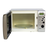
OUTER CASE REMOVAL
HIGH VOLTAGE COMPONENTS REMOVAL
POVVER TRANSFORMER REMOVAL
6. Remove the transformer.
MAGNETRON REMOVAL
1. Re-install the magnetron to the waveguide flange
by the four (4) mounting screws.
2. Install the air duct to the magnetron by one (1 )
mounting screw.
3. Re-connected the wire leads to the magnetron.
CAUTION:
WHEN REPLACING THE MAGNETRON,
BE SURE THE R.F. GASKET IS IN
PLACE AND
THE
MAGNETRON
MOUNTING SCREWS ARE TIGHTENED
SECURELY.
12
 Loading...