UPPER LATCH SWITCH, COOK (LATCH) SWITCH AND MONITOR SWITCH REMOVAL
1. Disconnect the oven from the power supply and remove the
Re-install
outer case.
1. Re-install each switch in its place.
2. Discharge the high voltage capacitor.
The upper latch switch is in the upper position and the
3. Disconnect the wire leads from the switch.
monitor switch is in the middle position and the cook
4. Remove the two (2) screws holding the latch hook from
(latch) switch’is in the lower position.
the oven cavity flange, and remove the latch hook.
5. - To remove the individual switch from the latch hook,
push outward the one (1) retaining tab holding the switch
in place.
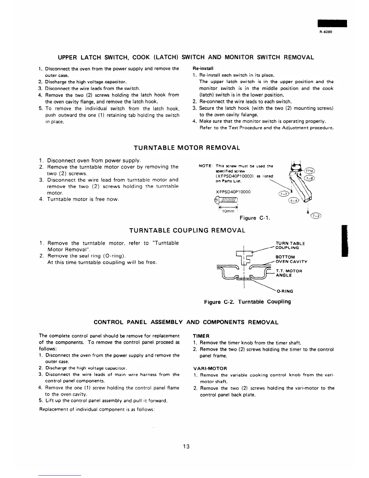
TURNTABLE MOTOR REMOVAL
1.
2.
3.
4.
Disconnect oven from power supply.
Remove the turntable motor cover by removing the
two (2) screws.
Disconnect the wire lead from turntable motor and
remove the two (2) screws holding the turntable
motor.
Turntable motor is free now.
TURNTABLE COUPLING REMOVAL
1.
2.
Remove the turntable motor, refer to “Turntable
Motor Removal”.
Remove the seal ring (O-ring).
At this time turntab1.e coupling will be free.
2. Reconnect the wire leads to each switch.
3. Secure the latch hook (with the two (2)
mounting screws)
to the oven cavity falange.
4. Make sure that the monitor switch is operating properly.
Refer to the Test Procedure and the Adjustment procedure.
NOTE: This screw must be used the
specified scrwv
(XFPSD40PlOOOO) as fist
on Parts List.
X FPSD40P10000
m
f7Gz
Figure C-l.
TURN TABLE
BOTTOM
OVEN CAVITY
Figure C-2. Turntable Coupling
CONTROL PANEL ASSEMBLY AND COMPONENTS REMOVAL
The complete control panel should be remove for replacement
of the components. To remove the control panel proceed as
follows:
TIMER
1. Disconnect the oven from the power supply and remove the
outer case.
1. Remove the timer knob from the timer shaft.
2. Remove the two (2) screws holding the timer to the control
panel frame.
2. Discharge the high voltage capacitor.
3. Disconnect the wire leads of main wire harness from the
control panel components.
VARI-MOTOR
1. Remove the variable cooking control knob from the vari-
motor shaft.
4. Remove the one (1) screw holding the control panel flame
2. Remove the two (2) screws holding the vari-motor to the
to the oven cavity.
control panel back plate.
5. Lift up the control panel assembly and pull it forward.
Replacement of individuai component is as follows:
13
 Loading...