DOOR REPLACEMENT
DOOR REPLACEMENT AND ADJUSTMENT
DOOR ADJUSTMENT
1. Disconnect the oven from the power supply and remove the
outer case.
2. Discharge the high voltage capacitor.
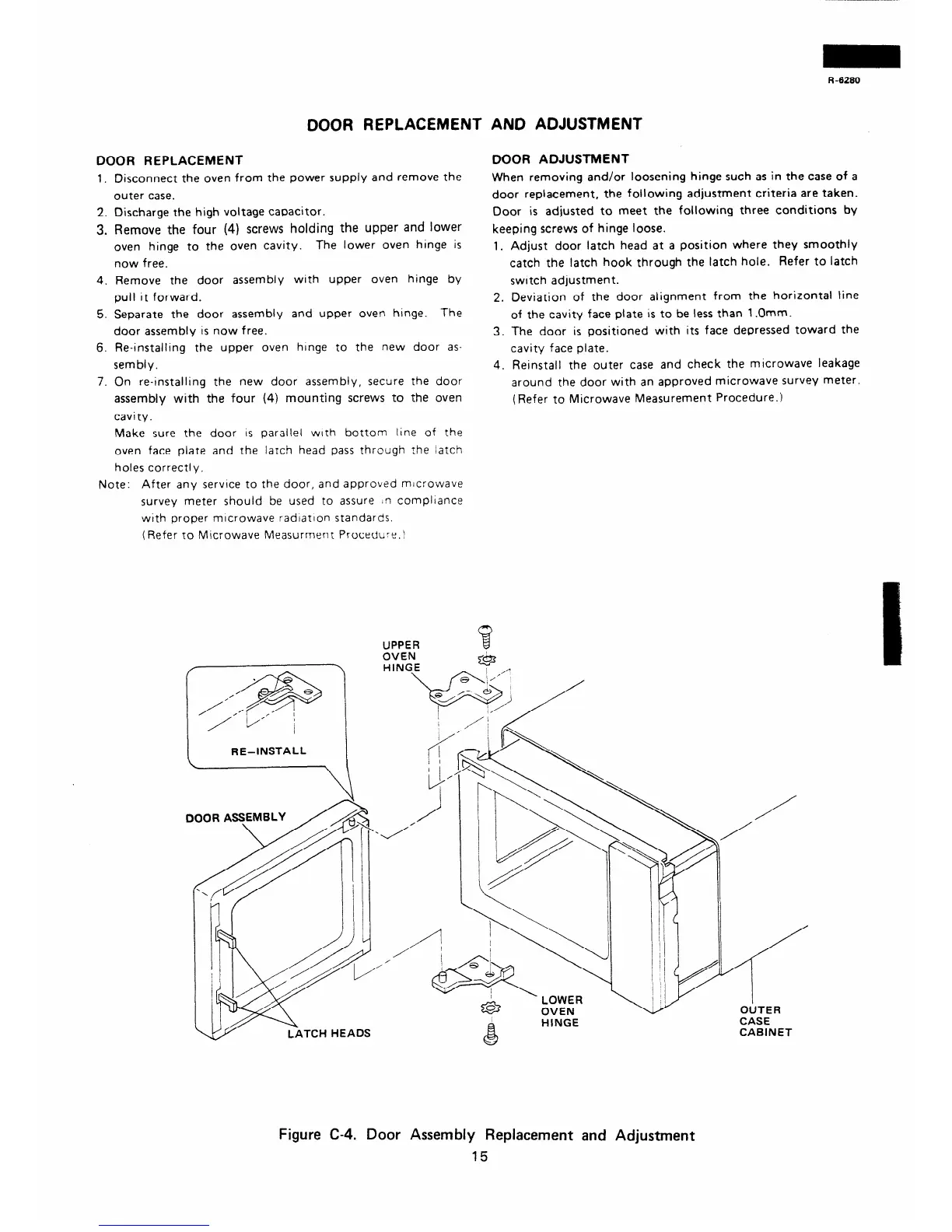
3. Remove the four (4) screws holding the upper and lower
oven hinge to the oven cavity.
The lower oven hinge is
now free.
4. Remove the door assembly with upper oven hinge by
pull It forward.
When removing and/or loosening hinge such as in the case of a
door replacement, the foilowing adjustment criteria are taken.
Door is adjusted to meet the following three conditions by
keeping screws of hinge loose.
1. Adjust door latch head at a position where they smoothly
catch the latch hook through the latch hole. Refer to latch
switch adjustment.
5. Separate the door assembly and upper oven hinge. The
door assembly IS now free.
6. Re-installlng the upper oven hinge to the new door as-
sembiy.
2. Deviation of the door alignment from the horizontal line
of the cavity face plate is to be less than 1 .Omm.
3. The door is positioned with its face depressed toward the
cavity face plate.
7. On re-installing the new door assembly, secure the door
assembly with the four (4) mounting screws to the oven
cavity.
4. Reinstall the outer case and check the mlcrowave leakage
around the door with an approved microwave survey meter.
(Refer to Microwave Measurement Procedure.)
Make sure the door IS parallel with bottom line of the
oven face plate and the latch head pass through the latch
holes correctly.
Note: After any service to the door, and approved mlcrowave
survey meter should be used to assure ln compliance
with proper mlcrowave radlatlon standards.
(Refer to Microwave Measurment Procedure.\
R -6280
,,-*
,y’/ /
RE-INSTALL
\
c
1 i
I/;”
DOOR ASSEMBLY
/
CASE
CABINET
Figure C-4. Door Assembly Replacement and Adjustment
15