R-677 - 29
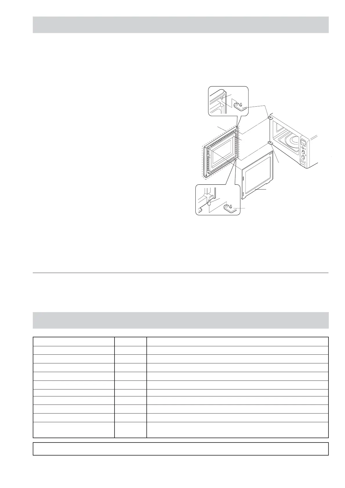
4. Hold the door panel to the door frame with four (4)
screws.
5. Catch two (2) pins of door panel on two (2) hole of upper
and lower oven hinges.
6. Re-install choke cover to door panel by pushing.
Note: After any service to the door;
(A) Make sure that door sensing switch and primary
latch switch are operating properly. (Refer to
chapter "Test Procedures".).
(B) An approved microwave survey meter should be
used to assure compliance with proper micro-
wave radiation emission limitation standards.
(Refer to Microwave Measurement Procedure.)
After any service, make sure of the following :
1. Door latch heads smoothly catch latch hook through
latch holes and that latch head goes through centre of
latch hole.
2. Deviation of door alignment from horizontal line of
cavity face plate is to be less than 1.0mm.
3. Door is positioned with its face pressed toward cavity
face plate.
4. Check for microwave leakage around door with an
approved microwave survey meter. (Refer to Micro-
wave Measurement Procedure.)
Note: The door on a microwave oven is designed to act
as an electronic seal preventing the leakage of
microwave energy from oven cavity during cook
cycle. This function does not require that door be
air-tight, moisture (condensation)-tight or light-
COMPONENT REPLACEMENT AND ADJUSTMENT PROCEDURE CONT...
PIN
PIN
LOWER
OVEN HINGE
UPPER
OVEN HINGE
LOWER
OVEN HINGE
CHOKE COVER
DOOR
PANEL
DOOR SUB
ASSEMBLY
tight. Therefore, occasional appearance of mois-
ture, light or sensing of gentle warm air movement
around oven door is not abnormal and do not of
themselves, indicate a leakage of microwave en-
ergy from oven cavity.
Figure C-8. Door Replacement
TEST DATA AT A GLANCE
PARTS SYMBOL VALUE / DATA
Special fuse F1 20A / 250V
Fuse F2 F 8A
Thermal cut-out (HVT) TC1 145°C Off / 115˚C On
Thermal cut-out (OVEN) TC2 150°C Off / 130˚C On
Grill heating element (top) GH1 Approx. 76 Ω / Insulation resistance > 10 MΩ
Bottom heating element GH2 Approx. 132 Ω / Insulation resistance > 10 MΩ
Oven lamp OL 230–240 V 25W
High voltage capacitor C AC 2100V 1.02µF
Magnetron MG Filament < 1Ω / Filament – chassis ∞ ohm.
Power transformer T Filament winding < 1Ω
Secondary winding Approx. 160 Ω / Primary winding Approx. 2.5 Ω
WARNING: DISCONNECT THE PLUG WHEN MEASURING RESISTANCE.