R-84STM - 13
TOUCH CONTROL / DESCRIPTION OF LSI
LSI(IXA094DR)
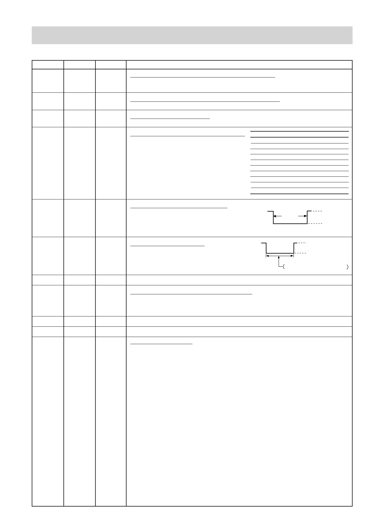
The I/O signal of the LSI(IXA094DR) are detailed in the following table.
Pin No. Signal I/O Description
Power output ON time OFF time
100 % 48 sec. 0 sec.
90 % 44 sec. 4 sec.
80 % 40 sec. 8 sec.
70 % 36 sec. 12 sec.
60 % 32 sec. 16 sec.
50 % 26 sec. 22 sec.
40 % 22 sec. 26 sec.
30 % 16 sec. 32 sec.
20 % 12 sec. 36 sec.
10 % 8 sec. 40 sec.
ON
OFF
During
cooking
L
GND
H.
(Convection or dual cooking)
ON
OFF
During cooking or for awhile after convection,
grill (top and bottom grill ) or dual.
L
GND
H.
38 XIN IN Internal clock oscillation frequency input setting.
The internal clock frequency is set by inserting the ceramic filter oscillation
circuit with respect to XOUT terminal.
39 XOUT OUT Internal clock oscillation frequency control output.
Output to control oscillation input of XIN.
40 VSS IN Power source voltage: -5V.
VC voltage of power source circuit input.
41 P27 OUT Bottom heating element driving signal.
To turn on and off the relay (RY4). "L"
level during grill cooking, convection
cooking or dual cooking, "H" level
otherwise.
The heater relay turns on and off
within a 48 second time base in
accordance with the special program
in LSI.
42 P26 OUT Convection motor driving signal.
To turn on and off shut-off relay(RY7). "L"
level during convection or dual cooking "H"
level otherwise. (Relay RY7 does not turn
on at preheating mode.)
43 P25 OUT Fan motor driving signal.
To turn on and off the fan motor relay RY6.
"L" level during cooking, or for a while after
convection, grill (top and bottom grill) or dual
cooking. "H" level otherwise.
44 P24 OUT Terminal not used.
45 P23 OUT Touch control transformer driving signal.
To turn on and off the shut off relay (RY5). If the oven has not been used for
more than 3 minutes, the relay RY5 will be turned off. The relay RY5 will be
turned on when the oven door is opened and closed.
46-48 P22-P20 OUT Terminal not used.
49-50 P17-P16 IN Terminal to change functions according to the model.
51-80 SEG39-SEG10 OUT Segment data signal.
Connected to LCD.
The relation between signals are as follows:
LSI signal (Pin No.) LCD (Pin No.) LSI signal (Pin No.) LCD (Pin No.)
SEG 0 (90) .................... SEG39 (51) SEG21 (69) ................. SEG19 (19)
SEG 1 (89) .................... SEG38 (50) SEG22 (68) ................. SEG18 (18)
SEG 2 (88) .................... SEG37 (49) SEG23 (67) ................. SEG17 (17)
SEG 3 (87) .................... SEG36 (48) SEG24 (66) ................. SEG16 (16)
SEG 4 (86) .................... SEG35 (47) SEG25 (65) ................. SEG15 (15)
SEG 5 (85) .................... SEG34 (46) SEG26 (64) ................. SEG14 (14)
SEG 6 (84) .................... SEG33 (45) SEG27 (63) ................. SEG13 (13)
SEG 7 (83) .................... SEG32 (44) SEG28 (62) ................. SEG12 (12)
SEG 8 (82) .................... SEG31 (43) SEG29 (61) ................. SEG11 (11)
SEG10 (80) ................... SEG30 (30) SEG30 (60) ................. SEG10 (10)
SEG11 (79) ................... SEG29 (29) SEG31 (59) ................... SEG 9 ( 9)
SEG12 (78) ................... SEG28 (28) SEG32 (58) ................... SEG 8 ( 8)
SEG13 (77) ................... SEG27 (27) SEG33 (57) ................... SEG 7 ( 7)
SEG14 (76) ................... SEG26 (26) SEG34 (56) ................... SEG 6 ( 6)
SEG15 (75) ................... SEG25 (25) SEG35 (55) ................... SEG 5 ( 5)
SEG16 (74) ................... SEG24 (24) SEG36 (54) ................... SEG 4 ( 4)
SEG17 (73) ................... SEG23 (23) SEG37 (53) ................... SEG 3 ( 3)
SEG18 (72) ................... SEG22 (22) SEG38 (52) ................... SEG 2 ( 2)
SEG19 (71) ................... SEG21 (21) SEG39 (51) ................... SEG 1 ( 1)
SEG20 (70) ................... SEG20 (20)