TEST PROCEDURES (CONT’D)
’ PROCEDURE
LETTER
r
G
1 (CONT’D)
!
H
I-
/
I
T
-~
COMPONENT TEST
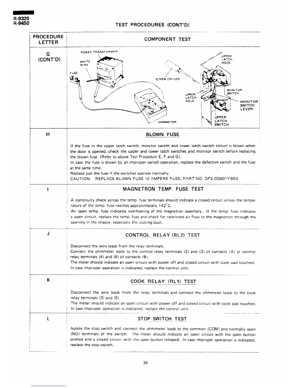
POWER TRANSFORMER
BLDWN FUSE
If the fuse in the upper latch switch, monitor switch and lower latch switch circuit is blown when
the door is opened, check the upper and lower latch switches and monitor switch before replacing
the blown fuse. (Refer to above Test Procedure E, F and G).
In case the fuse is blown by an improper switch operation, replace the defective switch and the fuse
at the same time.
Replace just the fuse if the switches operate normally.
CAUTION: REPLACE BLOWN FUSE 10 AMPERE FUSE, PART NO. QFS-CQOOIYBEO
+
MAGNETRON TEMP. FUSE TEST
A continuity check across the temp. fuse terminals should indicate a closed circuit uniess the tempe-
rature of the temp. fuse reaches approximatery 142°C.
An open temp. fuse indicates overheating of the magnetron assembly. If the temp. fuse indicates
a open circuit, replace the temp. fuse and check for restricted air flow to the magnetron through the
opening in the chassis, especrally the cooilng duct.
CONTROL RELAY (RLZI TEST
Disconnect the wire leads from the reiay rermrnals.
Connect the ohmmeter leads to the control relay terminais (2) and (3) of contacts (A) or control
relay terminals (4) and (5) of contacts (B).
The meter should indicate an open circuit with power off and closed circuit wrth cook pad touched.
In case improper operation is indicated, replace the control unit.
-
K
COOK RELAY (Rtlj TEST
--
L
Disconnect the wire leads from the relay terminais and connect the ohmmeter leads to the cook
relay terminals (3) and (5).
The meter should indicate an open circuit with power off and colsed circuit with cook pad touched.
In case improper operation IS indicated, replace the control unit.
______~
STOP SWITCH TEST
Isolate the stop switch and connect the ohmmeter leads to the common (COM) and normally open
(NO) termrnals of the switch.
The meter should Indicate an open circuit with the open button
pushed and a closed circuit wtth the open button released,
In case improper operation is indicated,
repiace the stop switch.
34