EasyManua.ls Logo

Sharp R-9380

Sharp R-9380
39 pages
To Next Page IconTo Next Page
Loading...
SHARP SERVICE MANUAL
S0705R9380J//
MICROWAVE OVEN
MODEL R-9380
In the interests of user-safety the set should be restored to its original
condition and only parts identical to those specified should be used.
(RDlGlOlU)
TABLE OF CONTENTS
Page
FOREWORD
. . . . . . . . . . . . . . . . . . . . . . . . . . . . . . . . . . . . . . . . . . . . . . . . . . . . . . . . . . . . . . . . . . . . . . . . . . . . . . . . . . . . . . . . . . . . . . . . . . . . . . . . . . . . . . . . . . . . . . . . ...............................
1
CAUTION,
MICROWAVE RADIATION
. . . . . . . . . . . . . . . . . . . . . . . . . . . . . . . . . . . . . . . . . . . . . . . . . . . . . . . . . . . . . . . . . . . . . . . . . . . . . . . . . . . . . . . . . . . . . . . . . . . . . . . . . .
1
PRODUCT
DESCRIPTION . . . . . . . . . . . . . . . . . . . . . . . . . . . . . . . . . . . . . . . . . . . . . . . . . . . . . . . . . . . . . . . . . . . . . . . . . . . . . . . . . . . . . . . . . . . . . . . . . . . . . . . . . . . . . . . . . . . . . . . . .......
2
OPERATION
. . . . . . . . . . . . . . . . . . . . . . . . . . . . . . . . . . . . . . . . . . . . . . . . . . . . . . . . . . . . . . . . . . . . . . . . . . . . . . . . . . . . . . . . . . . . . . . . . . . . . . . . . . . . . . . . . . . . . . . . ...............................
4
SERVICING
. . . . . . . . . . . . . . . . . . . . . . . . . . . . . . . . . . . . . . . . . . . . . . . . . . . . . . . . . . . . . . . . . . . . . . . . . . . . . . . . . . . . . . . . . . . . . . . . . . . . . . . . . . . . . . . . . . . . . . . . . . . . .........................
7
TOUCH CONTROL PANEL ASSEMBLY
. ..,..........,.............................................,.............*....................,....
15
COMPONENT
REPLACEMENT AND
ADJUSTMENT PROCEDURE
. . . . . . . . . . . . . . . . . . . . . . . . . . . . . . . . . . . . . . . . . . . . . . . . . . . . . .
22
MICROWAVE MEASUREMENT PROCEDURE
. . . . . . . . . . . . . . . . . . . . . . . . . . . . . . . . . . . . . . . . . . . . . . . . . . . . . . . . . . . . . . . . . . . . . . . . . . . . . . . . . . . . . . . . .
26
PICTORIAL
DIAGRAM
. . . . . . . . . . . . . . . . . . . . . . . . . . . . . . . . . . . . . . . . . . . . . . . . . . . . . . . . . . . . . . . . . . . . . . . . . . . . . . . . . . . . . . . . . . . . . . . . . . . . . . . . . . . . . . . . . . . . . . . . ..........
27
CONTROL
PANEL CIRCUIT
. . . . . . . . . . . . . . . . . . . . . . . . . . . . . . . . . . . . . . . . . . . . . . . . . . . . . . . . . . . . . . . . . . . . . . . . . . . . . . . . . . . . . . . . . . . . . . . . . . . . . . . . . . . . . . . . . . . . . . . . .
28
PRINTED
WIRING
BOARD
. . . . . . . . . . . . . . . . . . . . . . . . . . . . . . . . . . . . . . . . . . . . . . . . . . . . . . . . . . . . . . . . . . . . . . . . . . . . . . . . . . . . . . . . . . . . . . . . . . . . . . . . . . . . . . . . . . . . . . . . ..
29
PARTS
LIST
. . . . . . . . . . . . . . . . . . . . . . . . . . . . . . . . . . . . . . . . . . . . . . . . . . . . . . . . . . . . . . . . . . . . . . . . . . . . . . . . . . . . . . . . . . . . . . . . . . . . . . . . . . . . . . . . . . : . . . . . . . ..........................
30
PACKING
AND
ACCESSORIES
. . . . . . . . . . . . . . . . . . . . . . . . . . . . . . . . . . . . . . . . . . . . . . . . . . . . . . . . . . . . . . . . . . . . . . . . . . . . . . . . . . . . . . . . . . . . . . . . . . . . . . . . . . . . . . . . . . .
38
SHARPCORPORATION
Question and Answer IconNeed help?

Do you have a question about the Sharp R-9380 and is the answer not in the manual?

Sharp R-9380 Specifications

General IconGeneral
Capacity1.5 cu. ft.
TurntableYes
Weight47 lbs
Power Output900 W
Cooking ModesMicrowave, Grill, Combination
Turntable Diameter13 1/2 inches

Summary

FOREWORD

PRODUCT DESCRIPTION

EXPLANATION OF MICROWAVE COOKING

Explains how microwave energy cooks food by heating water molecules through friction.

SPECIFICATION

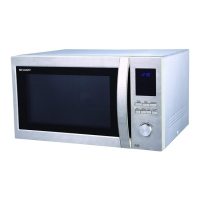
Lists technical details like power requirements, dimensions, and control features.

OVEN DIAGRAM

Auto-Touch Control Panel Layout

Details the layout and function of the touch-sensitive control interface.

OPERATION

DESCRIPTION OF OPERATING SEQUENCE

Outlines the step-by-step process of the oven's operation.

OFF CONDITION

Describes the state and basic functions when the oven is not in use.

COOKING CONDITION

Explains the general state when the oven is actively cooking.

VARIABLE COOKING POWER LEVELS

Describes different microwave power settings and their operational cycles.

DESCRIPTION AND FUNCTION OF COMPONENTS

MAGNETRON TEMP. FUSE

Explains the function of the fuse protecting the magnetron from overheating.

OVEN THERMAL CUT-OUT

Describes the safety device that shuts down the oven if overheating occurs.

DOOR MECHANISMS AND SWITCHES

Explains door opening, latch interlocks, and monitor switches.

SERVICING

TROUBLESHOOTING GUIDE

Lists common problems, causes, and corrections for oven malfunctions.

OFF CONDITION TROUBLESHOOTING

Lists issues and solutions when the oven is not powered or active.

COOKING CONDITION TROUBLESHOOTING

Lists issues and solutions occurring during oven operation.

TEST PROCEDURES

MAGNETRON ASSEMBLY AND POWER TESTS

Guides for testing magnetron, microwave output power, and related components.

TRANSFORMER, RECTIFIER, CAPACITOR, AND SWITCH TESTS

Procedures for testing key electrical components like transformers, rectifiers, capacitors, and switches.

FUSE AND THERMAL CUT-OUT TESTS

Specific tests for temperature fuses, monitor switches, blown fuses, and thermal cut-outs.

CONTROL PANEL AND PWB TESTS

Procedures for testing the touch control panel and printed wiring board.

PRINTED WIRING BOARD (PWB) OPEN PATTERN REPAIR

Steps for repairing open foil patterns on the PWB for power-on issues.

TOUCH CONTROL PANEL ASSEMBLY

OUTLINE OF TOUCH CONTROL PANEL

Gives an overview of the touch control panel's structure and units.

LSI AND CIRCUIT FUNCTIONS

Explains the roles of LSI, power source, stop switch, and relay circuits.

DESCRIPTION OF LSI

LSI(IZA135 DR) Pinout and Signals

Details the function of each pin on the LSI chip for interface signals.

SERVICING PRECAUTIONS AND TOOLS

Precautions for Handling Electronic Components

Advises on safe handling of sensitive electronic parts, especially LSI.

Touch Control Panel Servicing Procedures

Guides on how to service the touch control panel, including power supply considerations.

Servicing Tools Required

Lists necessary tools for maintaining the touch control panel assembly.

COMPONENT REPLACEMENT AND ADJUSTMENT PROCEDURE

OUTER CASE AND HIGH VOLTAGE COMPONENTS REMOVAL

Steps for removing the outer case and high voltage components.

MAGNETRON AND MOTOR REMOVAL

Instructions for removing the magnetron and turntable motor.

COOLING FAN MOTOR REMOVAL

Instructions for removing the cooling fan motor.

CONTROL PANEL ASSEMBLY AND SWITCH REMOVAL

Steps for removing control panel, latch, and monitor switches.

SWITCH ADJUSTMENT AND DOOR MECHANISMS

LATCH HEAD REMOVAL AND DOOR DISASSEMBLY

Explains how to remove the door latch head and disassemble the door.

DOOR REPLACEMENT AND ADJUSTMENT

DOOR REPLACEMENT

Step-by-step guide for replacing the oven door.

DOOR ADJUSTMENT

Instructions on adjusting the door for proper alignment and latching.

MICROWAVE MEASUREMENT

MEASUREMENT REQUIREMENT AND PREPARATION

Specifies performance standards and preparation for microwave leakage testing.

PARTS LIST

ELECTRICAL PARTS

Lists replacement parts for the electrical system.

CABINET PARTS

Lists replacement parts for the oven's exterior and structural components.

CONTROL PANEL PARTS

Lists replacement parts for the touch control panel and associated electronics.

SCREWS, NUTS AND WASHERS

Lists various fasteners and hardware used in the appliance.

REPLACEMENT PARTS LIST CROSS-REFERENCE

Provides a cross-reference for listed and used part numbers.

OVEN PARTS DIAGRAM

Illustrates the location of various internal oven components.

CABINET PARTS DIAGRAM

Illustrates the location of cabinet and exterior parts.

CONTROL PANEL PARTS DIAGRAM

Illustrates the location of control panel components.

DOOR ASSEMBLY PARTS DIAGRAM

Illustrates the location of components within the oven door assembly.

MISCELLANEOUS PARTS DIAGRAM

Illustrates the location of various other components not categorized elsewhere.

PACKING AND ACCESSORIES

Related product manuals