R-9380
DESCRIPTION AND FUNCTION OF COMPONENTS
MAGNETRON TEMP. FUSE
The temp. fuse located on the cavity top plate near the
magnetron to prevent damage to the magnetron if an over
heated condition develops in the tube due to cooling fan
failure, obstructed air ducts, dirty or blocked air intake, ect.
Under normal operation, the temp. fuse remains closed.
However, when abormally high temperatures are reached
within the magnetron the fuse will open at 115°C causing
the oven to shut down.
This is a fuse and it dose not reset.
OVEN THERMAL CUT-OUT
The oven thermal cut-out is located on the rear side of.steam
duct.
If is designed to prevent damege to the oven cavity
is foods in the oven catch fire due to overheating produced
by improper setting of cooking time etc.
Under normal
operation, this thermal cut-out remain closed.
However,
when abnormally high temperatures are reached within the
steam duct thermal cut-out will open causing the oven to
shut down.
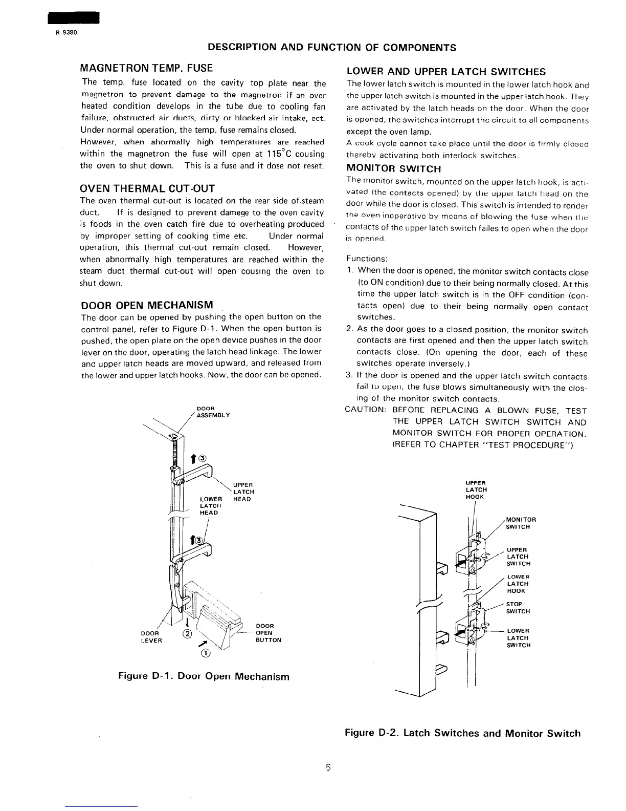
DOOR OPEN MECHANISM
The door can be opened by pushing the open button on the
control panel, refer to Figure D-l. When the open button is
pushed, the open plate on the open device pushes in the door
lever on the door, operating the latch head linkage. The lower
and upper latch heads are moved upward, and released from
the lower and upper latch hooks. Now, the door can be opened.
DOOR
/ASSEMBLY
UPPER
LATCH
HEAD
DOOR
OPEN
BUTTON
Figure D-l. Door Open Mechanism
LOWER AND UPPER LATCH SWITCHES
The lower latch switch is mounted in the lower latch hook and
the upper latch switch is mounted in the upper latch hook. They
are activated by the latch heads on the door. When the door
is opened, the switches interrupt the circuit to all components
except the oven lamp.
A cook cycle cannot take place until the door is firmly closed
therebv activating both interlock switches.
MONITOR SWITCH
The monitor switch, mounted on the upper latch hook, is actl-
vated (the contacts opened) by the upper latch head on the
door while the door is closed. This switch is intended to render
the Oven inoperative by means of blowing the fuse when the
COntaCtS of the upper latch switch failes to open when the door
is opened.
Functions:
1. When the door is opened, the monitor switch contacts close
(to ON condition) due to their being normally closed. At this
time the upper latch switch is in the OFF condition (con-
tacts open) due to their being normally open contact
switches.
2. As the door goes to a closed position, the monitor switch
contacts are first opened and then the upper latch switch
contacts close. (On opening the door, each of these
switches operate inversely.)
3. If the door is opened and the upper latch switch contacts
fail to open, the fuse blows simultaneously with the clos-
ing of the monitor switch contacts.
CAUTION: BEFORE REPLACING A BLOWN FUSE, TEST
THE UPPER LATCH SWITCH SWITCH AND
MONITOR SWITCH FOR PROPER OPERATION.
(REFER TO CHAPTER “TEST PROCEDURE”)
UPPER
LATCH
HOOK
MONITOR
SWITCH
UPPER
LATCH
SWITCH
LOWER
LATCH
HOOK
STOP
SWITCH
LOWER
LATCH
SWITCH
,
Figure D-2. Latch Switches and Monitor Switch
s
 Loading...