R-9380
COMPONENT REPLACEMENT AND ADJUSTMENT PROCEDURE
WARNING: To avoid possible exposure to microwave
energy;
A. Before operating oven
1. Make sure that unlatching door slowly is ac-
companied by a click indicating actuation of
monitor switch and latch switch.
2. Check visually door seal for arcing and damage.
B. Do not operate oven until after repair if any of fol-
lowing conditions exist;
1. Door does not close firmly against front of ap-
pliance.
2. There is a broken door hinge or support.
3. The door is bent or warped.
4. There is any defective parts in the latch, oven
door or microwave generating and transmission
assembly.
5.
There is any other visible damage to oven.
C. Do not operate oven
1. Without the RF gasket.
2. If door is not closed.
(RDA1204U)
OUTER CASE. REMOVAL
To remove the components, proceed as follows.
1. Disconnect oven from power supply.
4. Lift entire case from the unit.
2. Remove screws from rear and along the side edge
CAUTION: DISCHARGE
HIGH
VOLTAGE
of case.
CAPACITOR BEFORE TOUCHING ANY
3. Slide the entire case back about 3cm to free it from
OVEN COMPONENTS OR WIRING.
retaining clips on the cavity face plate.
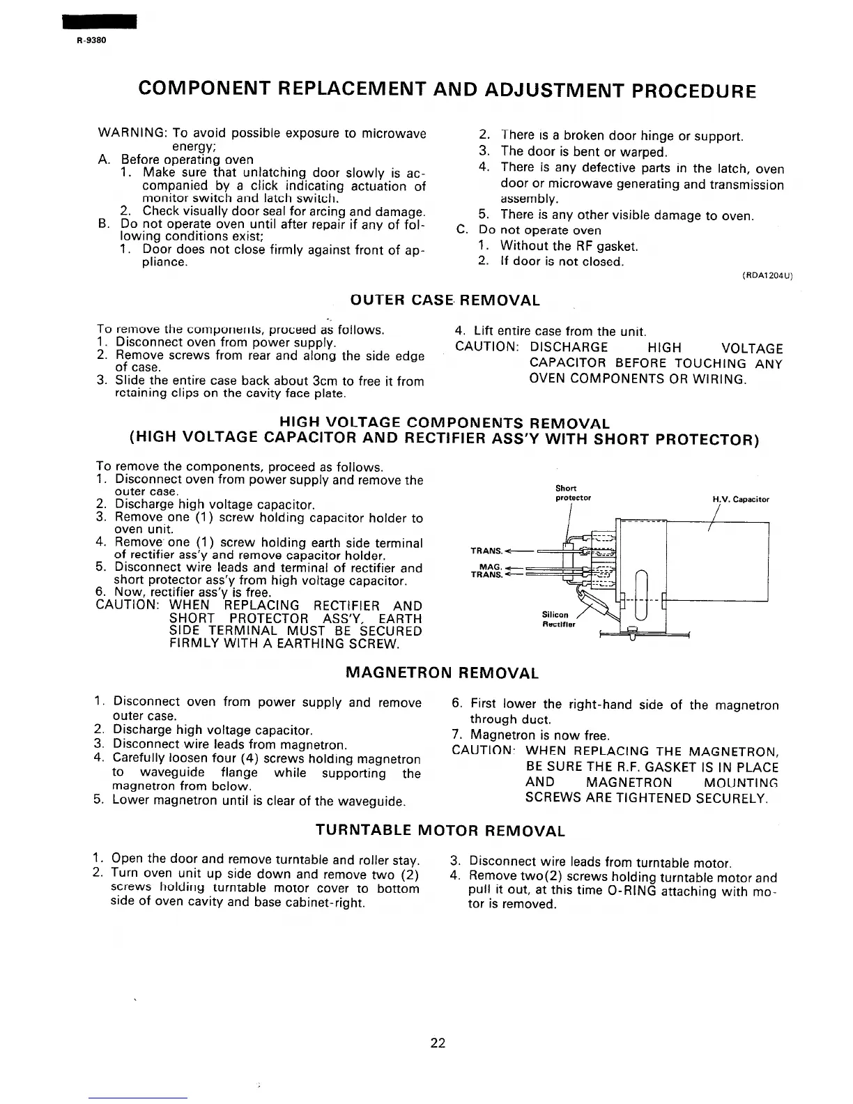
HIGH VOLTAGE COMPONENTS REMOVAL
(HIGH VOLTAGE CAPACITOR AND RECTIFIER ASS’Y WITH SHORT PROTECTOR)
To remove the components, proceed as follows.
1.
S:
4.
5.
6.
Disconnect oven from power supply and remove the
outer case.
Discharge high voltage capacitor.
Remove one (1) screw holding capacitor holder to
oven unit.
Remove, one (1) screw holding earth side terminal
of rectifier ass’y and remove capacitor holder.
Disconnect wire leads and terminal of rectifier and
short protector ass’y from high voltage capacitor.
a,
..I.
, . .
l\ow, rectmer assy IS Tree.
CAUTION: WHEN REPLACING RECTIFIER AND
SHORT PROTECTOR ASS’Y, EARTH
SIDE TERMINAL MUST BE SECURED
Short
protector
H.V. Capacitor
TRANS. -
MAG. c
TRANS. -
n
1.
2.
3.
4.
5.
1.
2.
FIRMLY WITH A EARTHING SCREW.
”
MAGNETRON REMOVAL
Disconnect oven from power supply and remove
outer case.
6. First lower the right-hand side of the magnetron
Discharge high voltage capacitor.
through duct.
Disconnect wire leads from magnetron.
7. Magnetron is now free.
Carefully loosen four (4) screws holding magnetron
CAUTION: WHEN REPLACING THE MAGNETRON,
to waveguide flange while supporting the
BE SURE THE R.F. GASKET IS IN PLACE
magnetron from below.
AND
MAGNETRON MOUNTING
Lower magnetron until is clear of the waveguide.
SCREWS ARE TIGHTENED SECURELY.
TURNTABLE MOTOR REMOVAL
Open the door and remove turntable and roller stay.
Turn oven unit up side down and remove two (2)
3. Disconnect wire leads from turntable motor.
screws holding turntable motor cover to bottom
4. Remove two(2) screws holding turntable motor and
side of oven cavity and base cabinet-right.
pull it out, at this time O-RING attaching with mo-
tor is removed.
22
 Loading...