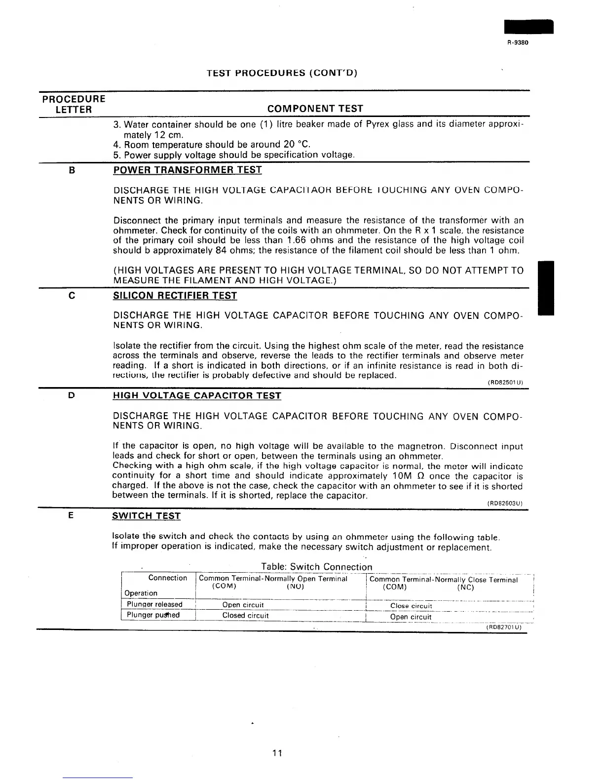
TEST PROCEDURES (CONT’D)
PROCEDURE
LETTER
COMPONENT TEST
3. Water container should be one (1) litre beaker made of Pyrex glass and its diameter approxi-
mately 12 cm.
B
4. Room temperature should be around 20 “C.
5. Power supply voltage should be specification voltage.
POWER TRANSFORMER TEST
DISCHARGE THE HIGH VOLTAGE CAPACITAOR BEFORE TOUCHING ANY OVEN COMPO-
NENTS OR WIRING.
Disconnect the primary input terminals and measure the resistance of the transformer with an
ohmmeter. Check for continuity of the coils with an ohmmeter. On the R x 1 scale, the resistance
of the primary coil should be less than 1.66 ohms and the resistance of the high voltage coil
should b approximately 84 ohms; the resistance of the filament coil should be less than 1 ohm.
(HIGH VOLTAGES ARE PRESENT TO HIGH VOLTAGE TERMINAL, SO DO NOT ATTEMPT TO
MEASURE THE FILAMENT AND HIGH VOLTAGE.)
C SILICON RECTIFIER TEST
DISCHARGE THE HIGH VOLTAGE CAPACITOR BEFORE TOUCHING ANY OVEN COMPO-
NENTS OR WIRING.
Isolate the rectifier from the circuit. Using the highest ohm scale of the meter, read the resistance
across the terminals and observe, reverse the leads to the rectifier terminals and observe meter
reading. If a short is indicated in both directions, or if an infinite resistance is read in both di-
rections, the rectifier is probably defective and should be replaced.
~RD62501 U)
D
HIGH VOLTAGE CAPACITOR TEST
DISCHARGE THE HIGH VOLTAGE CAPACITOR BEFORE TOUCHING ANY OVEN COMPO-
NENTS OR WIRING.
If the capacitor is open, no high voltage will be available to the magnetron. Disconnect input
leads and check for short or open, between the terminals using an ohmmeter.
Checking with a high ohm scale, if the high voltage capacitor is normal, the meter will indicate
continuity for a short time and should indicate approximately IOM R once the capacitor is
charged. If the above is not the case, check the capacitor with an ohmmeter to see if it is shorted
between the terminals. If it is shorted, replace the capacitor.
E
(RD82603U)
SWITCH TEST
Isolate the switch and check the contacts by using an ohmmeter using the following table
If improper operation is indicated, make the necessary switch adjustment or replacement.
Plunger released
Closed circuit
----_-.-L ._.._..___._ _ _~ ~~~ _..._
Open circuit
11
 Loading...