!O
L
Pin No.
Signal
I/O
Description
19
uo
NC
Terminal not used.
20
OUT
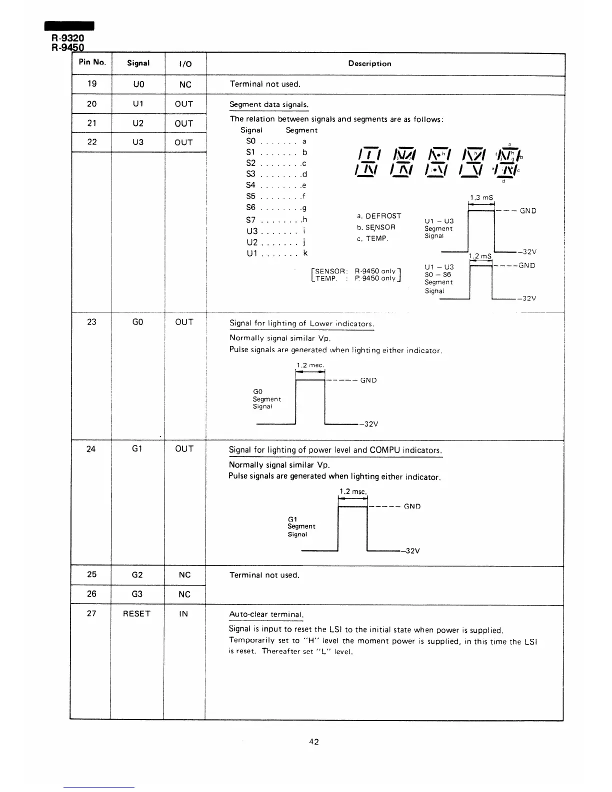
Segment data signals.
OUT /
The relation between signals and segments are as follows:
7
OUT 1
Signal Segment
SO . . . . . . . a
-
Sl . . . . . . . b
I
s2 . . . . . . . .c
ITI IE$ AT/ )\;r/ ‘/j\%/b
I
,
S3 . . . . . . . .d
Ir\l IRI I+/ I\/ elB/c
/
cl
!
S4 . . . . .e
I
s5 . . . , . . . .f
1.3 mS
Ul
u2 21
22
u3
S6 .......
.g
S7
....... .h
U3
....... i
U2
....... j
Ul
....... k
---
a. DEFROST
GND
Ul -u3
5. SE.NSOR
c. TEMP.
~~:nzn~ / j 32v
1.2 mS
Ul -u3
‘----GND
SENSOR
R-9450 only
TEMP.
I? 9450 only
1
so - S6
Segment
I I
SighI 1 32V
23 GO
OUT
Signal for lighting of Lower Indicators.
Normally signal similar Vp.
Pulse signals are generated when lighting either Indicator.
1.2 met.
.
Gl
w-_-e GND
-32V
24
OUT
Signal for lighting of power level and COMPU indicators.
Normally signal similar Vp.
Pulse signals are generated when lighting either indicator,
1.2 msc.
----- GND
-32V
G2
NC
Terminal not used.
25
26
G3
NC
IN Auto-clear terminal.
27
RESET
Signal is input to reset the LSI to the initial state when power is supplied.
Temporarily set to “H” level the moment power is supplied, in this time the LSI
is reset. Thereafter set “L” level.
42