R-9320
TURNTABLE MOTOR REMOVAL
1. Disconnect the oven from the power supply.
2. Remove the six (6) screws holding the base cabinet (8)
to the oven cavity and rear cabinet.
3. Shift the base cabinet (B) to the left to release the tab of
the base cabinet (B) from the base cabinet (A).
4. Remove the base cabinet (B).
6. Remove the four (4) screws holding the turntable motor
mounting plate to the oven cavity bottom.
6. Disconnect the wire leads from the turntable motor.
7. Remove the four (4) screws holding the turntable motor
to the mounting plate.
The motor is now free.
TURNTABLE ROLLER REMOVAL
1. Disconnect the oven from the power supply and remove
the outer case.
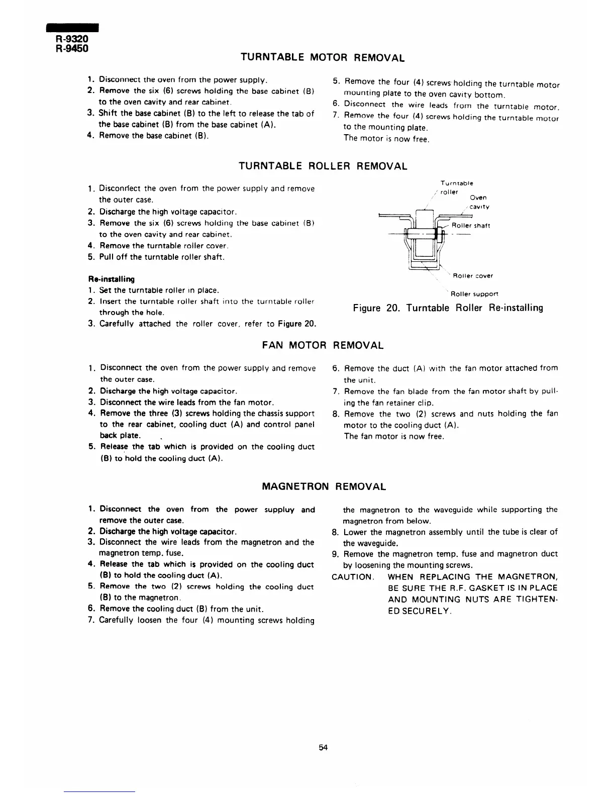
Turntable
roller
Oven
cavtty
2. Discharge the high voltage capacitor.
3. Remove the six (6) screws holding the base cabinet (B)
to the oven cavity and rear cabinet.
4. Remove the turntable roller cover.
5. Pull off the turntable roller shaft.
Re-installing
’ Roller cover
1.
2.
3.
Set the turntable roller in place.
Insert the turntable roller shaft into the turntable roller
through the hole.
Carefully attached the roller cover, refer to Figure 20.
FAN MOTOR REMOVAL
1.
2.
3.
4.
5.
Disconnect the oven from the power supply and remove
6. Remove the duct (A) with the fan motor attached from
the outer case.
the unit.
Discharge the high voltage capacitor.
7. Remove the fan blade from the fan motor shaft by pull-
Disconnect the wire leads from the fan motor.
ing the fan retainer clip.
Remove the three (3) screws holding the chassis support
8. Remove the two (2) screws and nuts holding the fan
to the rear cabinet, cooling duct (A) and control panel
motor to the cooling duct (A).
back plate. .
The fan motor is now free.
Release the tab which is provided on the cooling duct
(B) to hold the cooling duct (A).
MAGNETRON REMOVAL
1.
2.
3.
4.
5.
6.
7
Disconnect the oven from the power suppluy and
the magnetron to the waveguide while supporting the
remove the outer case.
magnetron from below.
Discharge the high voltage capacitor.
8. Lower the magnetron assembly until the tube is clear of
Disconnect the wire leads from the magnetron and the
the waveguide.
magnetron temp. fuse.
9. Remove the magnetron temp. fuse and magnetron duct
Release the tab which is provided on the cooling duct
by loosening the mounting screws.
(B) to hold the cooling duct (A). CAUTION.
WHEN REPLACING THE MAGNETRON,
Remove the two (2) screws holding the cooling duct
BE SURE THE R.F. GASKET IS IN PLACE
(B) to the magnetron.
AND MOUNTING NUTS ARE TIGHTEN-
Remove the cooling duct (B) from the unit.
ED SECURELY.
. . Carefully loosen the four (4) mounting screws holding
Roller support
Figure 20. Turntable Roller Re-installing
54