23
DESCRIPTION OF LSI
LSI(IXA036DR)
The I/O signal of the LSI(IXA036DR) are detailed in the following table.
Pin No. Signal I/O Description
1 AN0 IN Used for initial balancing of the bridge circuit (absolute humidity sensor). This input
is an analog input terminal from the AH sensor circuit, and connected to the A/D
converter built into the LSI.
2 P77 OUT Timing signal output terminal for temperature measurement(OVEN
THERMISTOR).
"H" level (GND) : Thermistor OPEN timing.
"L" level (-5V) : Temperature measuring timing. (Convection cooking)
3 P76 OUT Timing signal output terminal for temperature measurement(OVEN
THERMISTOR).
"H" level (GND) : Thermistor OPEN timing.
"L" level (-5V) : Temperature measuring timing. (Convection cooking)
4-5 P75-P74 OUT Terminal not used.
6 P73 IN Signal coming from touch key.
When any one of G9 line keys on key matrix is touched, a corresponding signal
from P10, P11, P12, P13, P14, P15, P16 and P17 will be input into P73. When no
key is touched, the signal is held at "L" level.
7 P72 IN Signal similar to P73.
When any one of G10 line keys on key matrix is touched, a corresponding signal
will be input into P72.
8 P71 IN Signal similar to P73.
When any one of G11 line keys on key matrix is touched, a corresponding signal
will be input into P71.
9 P70 IN Signal similar to P73.
When any one of G12 line keys on key matrix is touched, a corresponding signal
will be input into P70.
10-11 P57-P56 OUT Terminal not used.
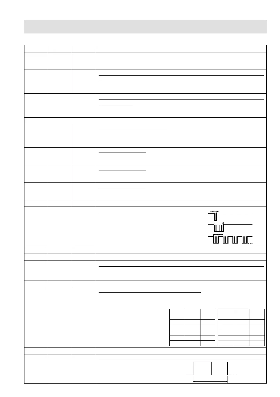
12 P55 OUT Signal to sound buzzer.
A: key touch sound.
B: Completion sound.
C: When the temperature of the oven cavity
reaches the preset temperature in the
preheating mode, or when the preheating
hold time (30 minutes) is elapsed.
13-17 P54-P50 OUT Used for initial balancing of the bridge circuit (absolute humidity sensor).
18 P47 OUT Terminal not used.
19 P46 IN Input signal which communicates the damper open/close information to LSI.
Damper opened; "H" level signal (0V:GND).
Damper closed; "L" level signal (-5V:VC).
20 P45 OUT Terminal not used.
21 P44 OUT Magnetron high-voltage circuit driving signal.
To turn on and off the cook relay
(RY2). In 100% operation, the
signals hold "L" level during
microwave cooking and "H" level
while not cooking. In other
cooking modes (70%, 50%, 30%,
10%) the signal turns to "H" level
and "L" level in repetition
according to the power level.
22 INT1 OUT Terminal not used.
23 INT0 IN Signal to synchronized LSI with commercial power source frequency(50Hz).
This is basic timing for time processing
of LSI.
A
B
C
H: GND
L
0.12 sec
2.4 sec
1.2 sec
1.2 sec
20 msec.
H : GND
L (-5V)
ON/OFF time ratio in Mi-
cro cooking
(a. 32second time base)
ON/OFF time ratio in Mi-
cro cooking
(a. 48second time base)
MICRO ON OFF
COOK
100% 32 sec. 0 sec.
70% 24 sec. 8 sec.
50% 18 sec. 14 sec.
30% 12 sec. 20 sec.
10% 6 sec. 26 sec.
MICRO ON OFF
COOK
100% 48 sec. 0 sec.
70% 36 sec. 12 sec.
50% 26 sec. 22 sec.
30% 16 sec. 32 sec.
10% 8 sec. 40 sec.