R-9HlO
Signal I/O
Description
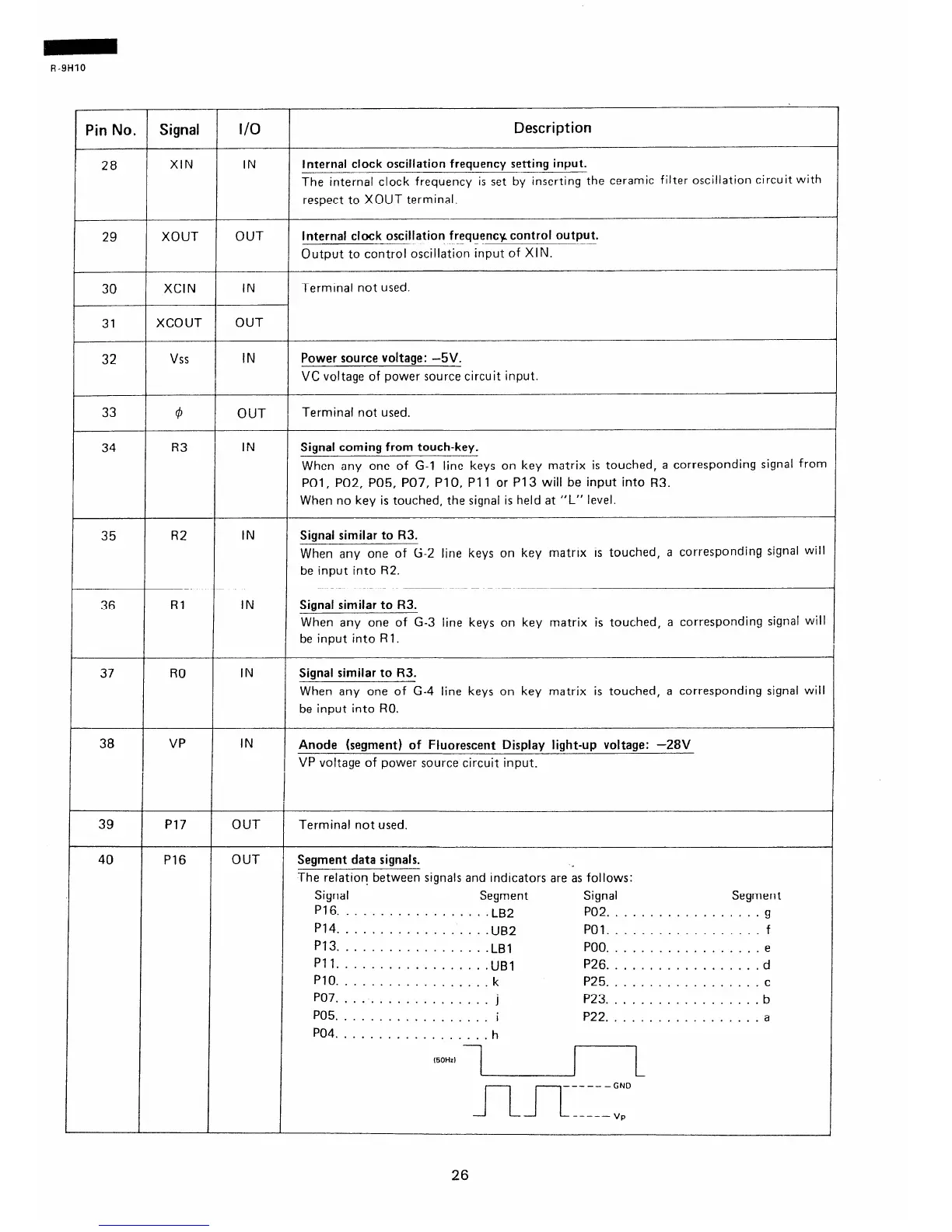
XIN IN
Internal clock oscillation frequency setting input.
The internal clock frequency is set by inserting the ceramic filter oscillation circuit with
respect to XOUT terminal.
29
XOUT OUT
Internal clock oscillation frequency control output.
Output to control oscillation input of XIN.
30
XCIN
IN
Terminal not used.
31
XCOUT
OUT
32
vss
IN Power source voltage: -5V.
VC voltage of power source circuit input.
33
F
34
35
@
OUT
Terminal not used.
R3
IN
Signal coming from touch-key.
When any one of G-l line keys on key matrix is touched, a corresponding signal from
POl, POZ, P05, P07, Pl 0, Pl 1 or P13 will be input into R3.
When no key is touched, the signal is held at “L” level.
R2
IN Signal similar to R3.
When any one of G-2 line keys on key matrix is touched, a corresponding signal will
be input into R2.
36
Rl IN
Signal similar to R3.
When any one of G-3 line keys on key matrix is touched, a corresponding signal will
be input into Rl.
37 RO
IN Signal similar to R3.
When any one of G-4 line keys on key matrix is touched, a corresponding signal will
be input into RO.
VP
38
39
40
IN
Anode (segment) of Fluorescent Display light-up voltage: -28V
VP voltage of power source circuit input.
P17 OUT Terminal not used.
P16
OUT Segment data signals.
The relation between signals and indicators are as follows:
Signal Segment
Signal
Segment
Pl6.
................ .LR2
PO2.
................. g
P14.
................ .Ul32
PO1
.................. f
P13.
................
.LBl
POO.
................. e
Pll..
............... .lJBl P26.
................. d
PlO.. ................
k
P25.
................. c
P07.
................. j P23.
................. b
P05.
................. i P22.
................. a
P04.. ................
h
(50Hzl
\
-J-u-r::;
26