EasyManua.ls Logo

Sharp SJ-A34S-SL User Manual

Sharp SJ-A34S-SL
33 pages
To Next Page IconTo Next Page
Page #1 background imageLoading...
Page #1 background image
SERVICE MANUAL
SJ-A20S/B21S/A24S/B25S/A28A/B27S/A31S/A34S-SL
No.S9902SJ22FTVTT
This document has been published to be used for
after sales service only.
The contents are subject to change without notice.
CONTENTS
Refrigerator-freezer
MODELS
SJ-A20S-SL
SJ-B21S-SL
SJ-A24S-SL
SJ-B25S-SL
SJ-A28S-SL
SJ-B27S-SL
SJ-A31S-SL
SJ-A34S-SL
DESTINATION T
Refer to "HFC-134a COOLING UNIT" Service Manual for handling this refrigerant.
R
efrigerant; HFC-134a
SJ-A28S-SL
SJ-B27S-SL
CHAPTER 1. SPECIFICATION
CHAPTER 2. DESIGNATION OF VARIOUS PARTS
[1] EXTERNAL DESCRIPTION........................... 2-1
[2] CONSTRUCTIONS........................................ 2-2
CHAPTER 3. DIMENTIONS
[1] OUTER DIMENTIONS AND
CLEARANCE ................................................. 3-1
[2] INNER DIMENTIONS .................................... 3-4
CHAPTER 4. LIST OF ELECTRICAL PARTS
CHAPTER 5. WIRING DIAGRAM
[1] WIRING DIAGRAM ........................................ 5-1
[2] ELECTRIC ACCESSORIES LAYOUT ........... 5-2
CHAPTER 6. FAILURE DIAGNOSIS
[1] OUTLINE OF CONTROL ............................... 6-1
[3] RE-SETTING OF MICROCOMPUTER AT
POWER FAILUR
E.......................................... 6-2
[4] D
IAGNOSIS METHOD OF FAILURE ............6-2
[5] CONVERSION TABLE ..................................6-3
[6] CIRCUIT DIAGRAM OF MAIN PWB .............6-4
CHAPTER 7. FUNCTIONS
[1] ADJUSTABLE TEMPERATURE
CONTROL .....................................................7-1
CHAPTER 8. ASSEMBLI NG PROCEDURES OF
MAIN PARTS AND CAUTIONS
[1] F-LOUVER ASS'Y (SJ-A20S/B21S/A24S/
B25S/A28S/B27S)
..........................................8-1
[3] R CONTROL COV. ASS'Y.............................8-7
[4] HOW TO REPLACE THE LAMP ...................8-9
[5] DEFROST HEATER ......................................8-10
CHAPTER 9. COOLING UNIT
[1] COOLING UNIT.............................................9-1
[2] LOCATION ............................
........................9-2
Parts Guide
[
2] F-LOUVER ASS'Y (SJ-A31S/A34S)...............8-4
[1] SJ-A20S/B21S/A24S/B25S/A28S/B27S........ 2-1
[2] SJ-A31S/A34S .......................................... 2-2
[3] PRECAUTION FOR USING LEAD-FREE
SOLDER........................................................5-3
[2] CHECK MODE OF DEFROST HEATER
(Forced Defrosting) ........................................ 6-1
SJ-F230G
SJ-F230G
SJ-F230G
Ag
Question and Answer IconNeed help?

Do you have a question about the Sharp SJ-A34S-SL and is the answer not in the manual?

Sharp SJ-A34S-SL Specifications

General IconGeneral
BrandSharp
ModelSJ-A34S-SL
CategoryRefrigerator
LanguageEnglish

Summary

Chapter 1. Specification

Model Specifications (SJ-A20S/B21S/A24S/B25S/A28S/B27S)

Details specifications for specific refrigerator models, including dimensions and ratings.

Model Specifications (SJ-A31S/A34S)

Provides specifications for SJ-A31S and SJ-A34S models, covering dimensions, volume, and ratings.

Chapter 2. Designation of Various Parts

External Description of Refrigerator Parts

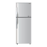
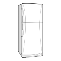
Identifies and labels the external components of the refrigerator.

Internal Constructions and Components

Details the internal structure and various components within the refrigerator.

Chapter 3. Dimensions

Outer Dimensions and Clearance Requirements

Provides detailed external measurements and required clearance for installation.

Inner Dimensions of Refrigerator Compartments

Specifies the internal dimensions for both freezer and refrigerator compartments.

Chapter 4. List of Electrical Parts

Electrical Components and Specifications

Lists key electrical parts, their type names, ratings, and specifications.

Chapter 5. Wiring Diagram

Refrigerator Wiring Diagram

Illustrates the electrical connections and wiring schematic of the refrigerator.

Electric Accessories Layout

Shows the physical placement and layout of electrical accessories within the unit.

Precautions for Using Lead-Free Solder

Provides guidelines and safety precautions for working with lead-free solder during repairs.

Chapter 6. Failure Diagnosis

Outline of Control System Operations

Explains the basic control logic for compressor ON/OFF and defrosting cycles.

Defrost Heater Check Mode (Forced Defrosting)

Describes the procedure to manually check the defrost heater's operation.

Microcomputer Reset Procedure After Power Failure

Details how the microcomputer resets after power interruptions and its implications.

Refrigerator Failure Diagnosis Methods

Outlines systematic steps for diagnosing refrigerator malfunctions and checking components.

Thermistor Conversion Table

Provides a conversion table for thermistor resistance values versus temperature.

Main PWB Circuit Diagram

Presents the detailed circuit diagram for the main printed wiring board (PWB).

Chapter 7. Functions

Adjustable Temperature Control System

Explains how to adjust temperature settings for freezer and refrigerator compartments.

Chapter 8. Assembling Procedures of Main Parts and Cautions

F-Louver Unit Assembly (Models SJ-A20S-SJ-A28S/B27S)

Procedures for assembling the F-louver unit, including fan motor and EV-cover.

F-Louver Unit Assembly (Models SJ-A31S/A34S)

Procedures for assembling the F-louver unit for SJ-A31S and SJ-A34S models.

R Control Cover Assembly

Step-by-step instructions for assembling the R Control Cover unit.

Lamp Replacement Procedure

Instructions for safely removing and replacing the refrigerator's interior lamp.

Defrost Heater and Evaporator Procedures

Guides on removing the evaporator and replacing the defrost heater.

Chapter 9. Cooling Unit

Cooling Unit Brazing and Repair Notes

Important notes and precautions for brazing iron pipes in the cooling unit.

Refrigerant Circuit Component Locations

Identifies the locations of key components within the refrigerant circuit.

Related product manuals