EasyManua.ls Logo

Sharp SJ-P63M-SL User Manual

Sharp SJ-P63M-SL
44 pages
To Next Page IconTo Next Page
Page #1 background imageLoading...
Page #1 background image
1
SJ-P58M/58M
SJ-P63M/63M
SJ-P68M/68M
SERVICE MANUAL
S5310SE68CPUE
SHARP CORPORATION
TABLE OF CONTENTS
page
ENERGY LABEL................................................................................................................................................2
INSTALLATION .................................................................................................................................................2
CAUTIONS AND INFORMATIONS ...................................................................................................................3
SPECIFICATIONS .............................................................................................................................................4
DESIGNATION OF VARIOUS PARTS ..............................................................................................................5
THE FICHE ........................................................................................................................................................6
LIST OF ELECTRICAL PARTS .........................................................................................................................7
DIMENSIONS ....................................................................................................................................................8
WIRING DIAGRAM ..........................................................................................................................................10
FUNCTIONS ....................................................................................................................................................15
ASSEMBLING PROCEDURES OF MAIN PARTS AND CAUTIONS ..............................................................19
COOLING UNIT ...............................................................................................................................................27
REPLACEMENT PARTS LIST ........................................................................................................................29
Refrigerant; HFC-134a
Refer to "HFC-134a COOLING UNIT" Service Manual for handling this refrigerant.
DESTINATION ......................... E
In the interests of user-safety (Required by safety regulations in some
countries) the set should be restored to its original condition and only
parts identical to those specified should be used.
REFRIGERATOR-FREEZER
MODELS
SJ-P58M-GY/SL/WH
SJ-58M-GY/SL/WH
SJ-P63M-GY/SL/WH
SJ-63M-GY/SL/WH
SJ-P68M-GY/SL/WH
SJ-68M-GY/SL/WH
Plasmacluster
SJ-P58M
SJ-P63M
SJ-P68M
SJ-58M
SJ-63M
SJ-68M
This equipment complies with the
requirements of Directives
96/57/EC, 89/336/EEC and 73/23/EEC
as amended by 93/68/EEC.
Question and Answer IconNeed help?

Do you have a question about the Sharp SJ-P63M-SL and is the answer not in the manual?

Sharp SJ-P63M-SL Specifications

General IconGeneral
BrandSharp
ModelSJ-P63M-SL
CategoryRefrigerator
LanguageEnglish

Summary

REFRIGERATOR-FREEZER MODELS

ENERGY LABEL

Usage of the ENERGY LABEL

Instructions for attaching the energy label to the refrigerator display.

INSTALLATION

Free standing type Installation Guidelines

Specifies clearance requirements for proper ventilation of the refrigerator.

CAUTIONS AND INFORMATIONS

Operational Cautions and Normal Sounds

Details common issues, cleaning advice, and normal operating sounds.

SPECIFICATIONS

DESIGNATION OF VARIOUS PARTS

External Description and Construction Diagrams

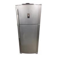
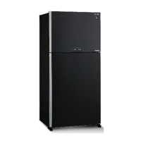
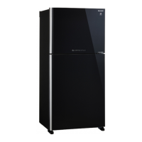
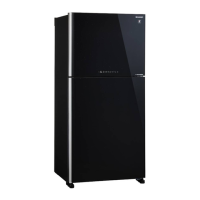
Illustrates external parts and internal construction of the refrigerator.

THE FICHE (according to ANNEX II : 94/2/EC)

LIST OF ELECTRICAL PARTS

DIMENSIONS

Outer Dimensions and Clearance

Provides external measurements and required space for installation.

INNER DIMENSIONS

Internal Compartment Dimensions

Details the interior space measurements of refrigerator and freezer compartments.

WIRING DIAGRAM

Wiring Diagram for SJ-P58M,P63M,P68M Models

Electrical schematic illustrating connections for specific refrigerator models.

Wiring Diagram for SJ-58M,63M,68M Models

Electrical schematic for alternative refrigerator models.

Electric Accessories Layout Diagrams

Diagrams showing the placement of electrical accessories for different models.

Main PWB Circuit Diagram

Detailed circuit diagram for the main control board.

FUNCTIONS

Adjustable Temperature Control

Explains freezer and refrigerator temperature settings and their effects.

Temperature Control Reference Values

Provides expected temperature readings based on control knob settings.

DEFROSTING

Defrosting Operation and Melted Frost Handling

Describes the automatic defrosting process and where melted frost goes.

Automatic Defrosting Circuit Diagrams

Illustrates the defrosting cycle stages with circuit diagrams.

Troubleshooting References and Dew Prevention

Discusses common defrost issues, thermo-fuse function, and dew prevention.

Initial Starting and Defrost Device Inspection

Guides on checking initial startup and verifying defrost system operation.

PLASMACLUSTER SYSTEM

Plasmacluster Function and Panel Operation

Explains the Plasmacluster ionizer and how to operate its panel.

Plasmacluster Control Logic

Details the conditions and timing for Plasmacluster operation.

ASSEMBLING PROCEDURES OF MAIN PARTS

R-CONTROL COV. ASSEMBLY Procedure

Step-by-step guide for assembling the R-Control Cover unit.

Sealer Application and Ionizer-K Fixing

Instructions for applying sealers and mounting the Ionizer-K component.

Defrost Timer & R Fan Thermo Assembly

Covers fixing defrost timer and R fan thermo. assembly to the R-C box.

R LAMP BOX ASSEMBLY Steps

Details the assembly process for the R lamp box unit.

Lamp and Lamp Socket Assembly

Instructions for fixing the lamp and socket into the R lamp box.

R-Fan Motor and Fan Assembly

Steps for assembling the R-fan motor and fan components.

E.V COVER ASSEMBLY and Sealer Application

Instructions for assembling the E.V cover and applying its sealers.

Fan Motor and Fan Fixing Procedures

Steps for fixing the fan motor and fan components.

Setting Fan Motor, Defrost Thermo, Fuse

Instructions for setting fan motor, defrost thermostat, and fuse assemblies.

Setting of F-thermostat

Steps for forming and setting the F-thermostat capillary tube.

COOLING UNIT

Cooling Unit Diagram and Refrigerant Flow

Illustrates the cooling unit components and refrigerant flow path.

Location of Cooling Unit Components

Shows the layout and connection points of cooling unit parts.

REPLACEMENT PARTS LIST

HOW TO ORDER REPLACEMENT PARTS

DOOR PARTS

CABINET PARTS

Related product manuals