18
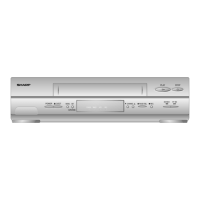
VC-A10/A10S/A500
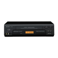
VC-A50/A50S/A50SB
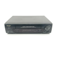
VC-A60/A75/A80S
Figure 4-22.
• Replacement
1. Solder the removed PWB to the new head assembly.
2. Adjust the height from the A/C head arm (lower surface)
to the A/C head plate to 10.8mm with slide calipers. (3
places of azimuth screw section, tilt screw section and A/
C head front section) (See the figure below.)
3. Align the left end of gear of A/C head arm with the
punched mark of chassis, tentatively tighten the screws
1 so as to ensure smooth motion of A/C head arm.
Tightening torque must be 0.45 ± 0.05N·m (4.5 ±
0.5kgf·cm).
4-15 REPLACEMENT OF A/C (AUDIO/CONTROL)
HEAD
1. In eject position unplug the power cord.
• Removal
1. Take out FFC holder from main chassis.
(Push 3 hooking point and pull-up the
holder).
2. Remove the screws 123, Tilt screw.
3. Unsolder the PWB fitted to the A/C head.
Notes:
1. When replacing, never touch the head. If you touched,
clean with the cleaning liquid.
2. When removing the screw 3, take care so that the
spring may out.
Figure 4-23.
Note:
1. If the screw 1 is tighten tentatively too loose, the
azimuth and height of A/C head may change when they
are finally tightened. Therefore care must be taken.
2. After completion of A/C head be sure to adjust tape
running. (Execute the running adjustment by the method
described in 4-17.)
Figure 4-21.
Height screw
Left end of A/C head arm gear
Punched line mark on chassis
1
3
1
2
A/C head screw
Azimuth spring
Height adj. screw
A/C head PWB ass'y
(with A/E)
Tilt screw
Height Adj. spring
A/C head PWB
Azimuth adj. screw
*Derection designation.
(The bottom part is big.)
A/C head plate
10.8mm
A/C head FFC
A/C FFC holder
Solder
A/C head PWB
New A/C head ass'y
A/C head plate
*Fit the groove of FFC to
the boss of the holder.
AC Head
FFC
Holder