Do you have a question about the Sharp VC-MH705HM/LM and is the answer not in the manual?
Specific guidelines for handling sensors, photocouplers, and cam switches.
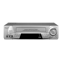
Comprehensive details on video, audio, and mechanical aspects of the VCR.
Step-by-step guide to disassembling the main components of the unit.
Specific instructions and precautions for reassembling the unit's parts.
Diagrams and lists identifying key mechanical parts from top and bottom views.
Guide to electrical adjustments, instruments, and test points.
Procedures for adjusting various circuits including servo, Y/C, audio, tuner, timer, and power.
Flowchart detailing the VCR mechanism's operational sequence.
Guide for diagnosing and resolving mechanism-related faults.
Flowcharts for power, system control, key input, and cassette/loading issues.
Flowcharts for motor controls, audio/video signals, and recording problems.
Flowcharts for servo systems, NICAM/IGR, decoder, and other specialized circuits.
Procedures for replacing IC710 and reprogramming its memory function.
Procedures for setting jumpers and REC current via the TV screen.
Table detailing ROM data for various models and jumper settings.
Diagrams illustrating system overview, signal paths, audio, and power circuits.
Schematic and PWB layout for the main circuit section (1-1).
PWB layout for the EUR-TERM circuit.
Guide to identifying transistors/diodes and categorized part listings.
Instructions on how to correctly order replacement parts.
Illustrated diagram of mechanism chassis components assembly.
Exploded views of mechanical and front panel parts by model.
Illustration and list of accessories for packing the VCR unit.
| Number of heads | 4 |
|---|---|
| Hi-Fi Stereo | Yes |
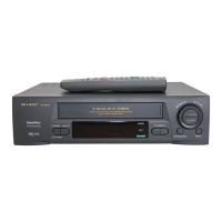
| Remote Control | Yes |
| Recording Formats | VHS |
| Tuner | Yes |
| Playback Formats | VHS |