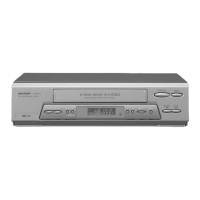
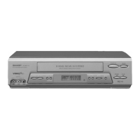
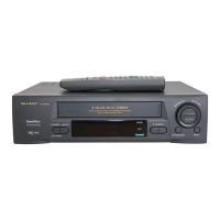
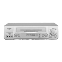
VC-MH80
VC-MH90
PRECAUTIONS IN PART REPLACEMENT
When servicing the
unit
with
power
on,
be
careful to the section
marked
white
all
over.
This
is
the
primary
power
circuit which
is
live.
When checking the soldering side in the tape travel mode, make sure first that the tape has
b;en
loaded and
then turn over the PWB with due care to the primacy power circuit.
Make readjustment, if needed after replacement of part, with the mechanism and its PWB in position in the
main frame.
(1) Start and end sensors: D710 and D709.
Insert the sensor’s projection deep into the upper hole of the holder
(LHLDZ1893AJOO).
Referring to the
PWB, fix the sensors tight enough.
(2) Photocoupler
RH-FX0005GEZZ:
IC901
Refer to the symbol on the PWB and the anode marking of the part.
(3) Cam switches A and
B
(RH-PX0231GEZZ)
:
D714 and
D713.
Adjust the notch of the part to the white marker of the symbol on the PWB. Do not allow a6y looseness.
(4) Take-up and supply sensors
(RH-PX0232GEZZ):
D712 and D711.
.
Be careful not to confuse the setting direction of the parts in reference to the symbols on the PWB. Do not
allow any looseness.
(5) Diode bridge (RH-DX0083GEZZ): D901.
Adjust the
+
marking of the pat-t to the
symbol’scathode
marking on the PWB.
2