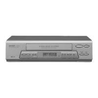
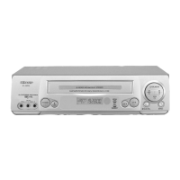
VC-MH80
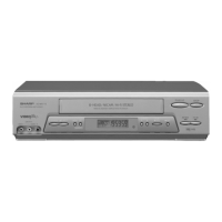
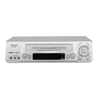
VC-MH90
Y/C
ClRCUIT.ADJUSTMENT
CHECKING OF VIDEO E-E LEVEL
Input signal
EIA
colour bar (1
.OVp-p)
Test point
VIDEO OUT jack
7
Il.o+o.lvp-p
1
Specification
1
i
.
2.
3.
Connect a 75 ohm terminating resistor to the
VIDEO OUT jack and connect an oscilloscope
across this terminating resistor.
(See Note below.)
Feed a colour bar signal to the VIDEO IN jack.
Make sure that the E-E signal amplitude is 1.0
Vp-p
as shown in Figure
5-4.
. . . . . . . . . .
. . .
. .
Note:
Figure
5-4.
If the 75 ohm terminating resistor is missing, the
signal amplitude will be doubled.
CHECKING OF WHITE CLIP LEVEL
Measuring
Oscilloscope
instrument
Mode
E-E or Record
Input signal
-
EIA
colour bar (1
.OVp-p)
:
Test point
Pin (48) of
IC201,
GND
Specification 190
f
5% (See note below)
1. Connect a oscilloscope to Pin (48) of
IC201
and
GND.
2. Feed the colour bar signal to the VIDEO IN jack
and set the unit in E-E or recording mode.
3. Make sure that the overshoot of the video signal
isclipped
at 190% as shown in Figure
5-5.
, ,
b-f
.
.
.
.
.
“f
?A
I
SYNCTIP
I
I
’
100%
WHITE
.
.
.
.
.
.
.
.
.
.
.
.
.
.
.
.
.
.
.
.
.
.
.
.
.
.
.
.
.
.
.
.
..-
WHITE
CLIP
LEVEL
Figure
5-5.
Note:
From sync tip to white peak, the level is 100%.
The white clip level is 90% above the white level.
CHECKING OF RECORD LEVEL
I
Measuring
I
Osci
I
loscope
instrument
I
Mode
t
Record mode (PAL LP mode)
-------------------______
Record mode (SECAM LP mode)
(VC-MH80 ONLY)
Input signal
PAL colour bar signal (1
.OVp-p)
.-------------------------.
SECAM colour bar signal
(1
.OVP-PI
(VC-MH80 ONLY)
I
Control
I
R224 (REC-Y LEVEL)
I
Chroma (Red)
:
44
5
8mVp-p
.--------------------------
Chroma (Cyan)
:
44
+
8mVp-p
(VC-MH80 ONLY)
__-------------------------
Sync tip: 140
i
1 SmVp-p
1.
2.
3.
4.
5.
6.
7.
8.
9.
Feed the PAL colour bar signal to the VIDEO IN
jack and set the unit in recording mode.
Connect the oscilloscope to test points TP301
(Sig.) and TP302 (GND).
Set the unit in the LP recording mode.
Turn R224 (REC-Y LEVEL) to minimize the FM
luminance signal.
Make sure so that the amplitude of the chroma
(red) portion is specified as shown in Figure
5-6
(a).
In the next place put the unit in SECAM mode
with the feed the SECAM colour bar signal to the
VIDEO IN jack and set the unit in recording
mode. (VC-MH80 ONLY)
Make sure so that the amplitude of the chroma
(cyan) portion is specified as shown in Figure
5-6
(c).
(VC-MH80 ONLY)
Again feed the PAL colour bar signal to the
VIDEO IN jack and set the unit in recording
mode.
Adjust R224 (REC-Y LEVEL) so that the amplitude
of sync tip portion is specified as shown in Figure
5-6
(b).
Red
. .
;:
‘i;$g
,,,
,.....
::
y:‘:
;‘:‘:‘:‘:‘:’
.‘:~:::::L::~:::~~:~:;:
:.:.,,,.,
.‘.,Yi..
.,
..,__.
..
. . .
. . . .
...
.._..
.
.
. . .
.
..C
i.
:::::::~:~.:::p:.:.:.:.:.:.:.:.:
ma
ilBQIX:~~fi:
Sync.
tip
~~~~~~~~~~~~~
..a
. ..A...
.
.
.
.
.
iv
.
..L
.
.
. . . .
..I
~~~~~~~~~~
Level
~~~
::i:j::.~.:.:.:.:.:.:.:.:.:.:
/.................
.-...
-.~.~.>:.>>i:.:.:.:
.,..:,;
,~,:,~,f)ff:.:.:.,,,.,.,,,
':':':':,:.~:.:.:.:::::::::::::::::::::::::
.::A:'.~>,.):,>
,...(,",,,.,',I',~.f'..,.
::::::::+:xr
'~.~....,.....i.,.
..,,,,,,......,.,.,.
'.'.
.
.
.
.
.
..A.
.
.
..i..
t
,..:.:.:.:
',',',.,',',',:,:,':
t
:,.,.,,,.,
eg&-@
'.'.~.“::.:q.:
.':::::::::::::::::::.:
.
.
.
.
.
.
.,
.:+:.:.)"~
:,
,i$z.w
Figure
5-6(a).
Figure
5-6(b).
39
 Loading...