VT-341
8X
W-51
18X
l
Removal
1.
Unsolder the cassette switch connectors (No.
16,
17)
from the start sensor
PWB.
Start sensor
PWB
Cassette switch
connector
Figure
l-3.
2.
Lift the start sensor
PWB
pressing the two start
sensor
PWB
fixing hooks inward.
Start sensor
PWB
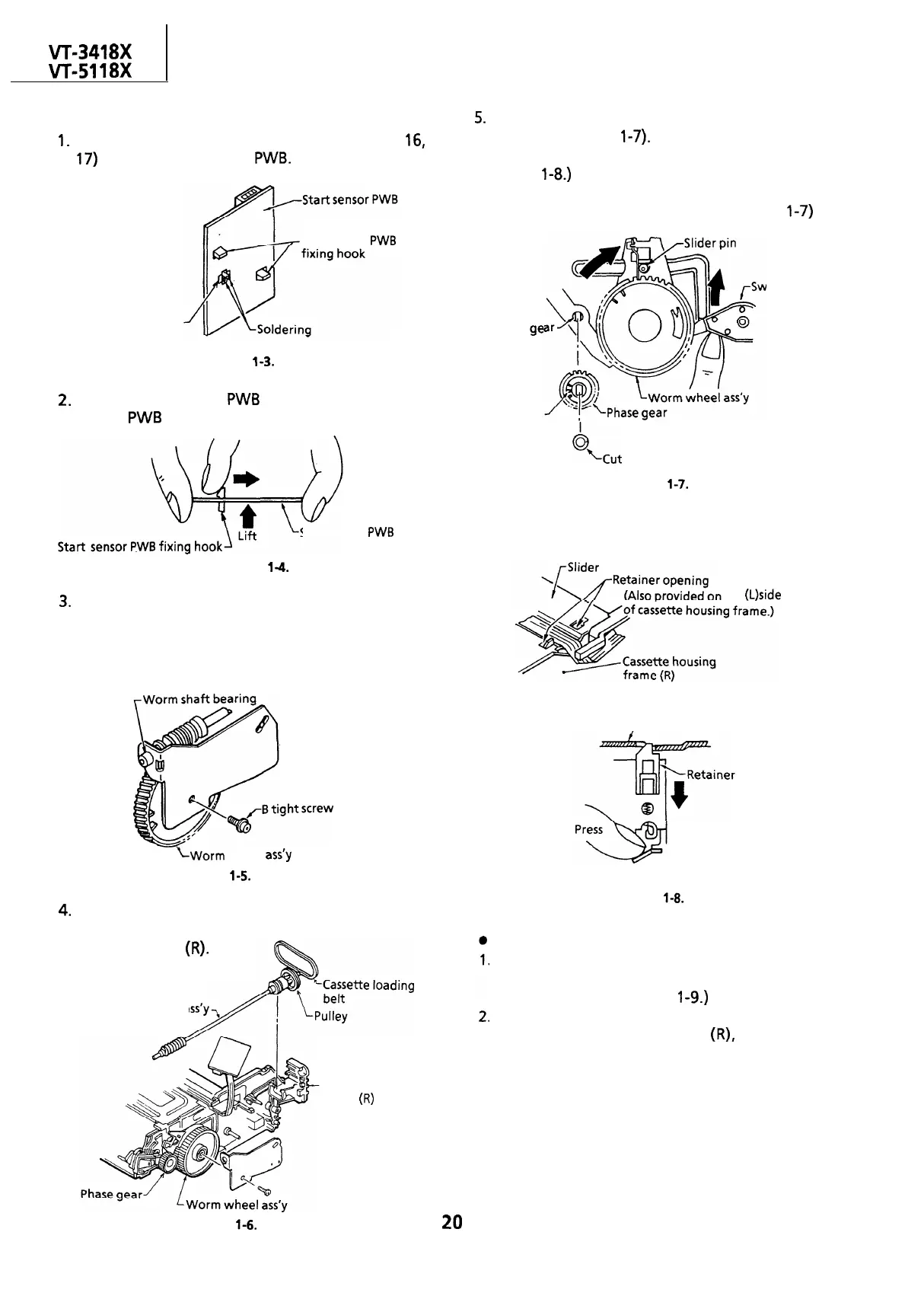
5.
6
Place the slider pin just above the worm wheel
assembly (Figure l-7). (The retainer of the slider
is locked at two positions. So unlock it as in the
Figure
1-8.)
Pull out the worm wheel assembly toward you
pressing the switch lever upward. (Figure
l-7)
itch lever
Phase
ge
shaft
Tally mark
‘%ut
washer
Figure
l-7.
3.
4.
Figure
l-4.
Unscrew one B tight screw to detach the worm
bracket.
Note:
The worm shaft bearing can easily come-out of
position. So be careful not to lose it.
-Worm bracket
LWorm
wheel
ass’y
Figure
l-5.
Remove the worm shaft assembly, pulley, and
cassette loading belt all from the cassette
housing frame
(R).
Worm shaft a
Cassette housing
frame
(R)
Figure
l-6.
20
the
(L)side
/-Slider
Cassette housing frame
(R)/(L) side
Figure
l-8.
Reassembly
Turn the phase gear clockwise until the slider
comes to a halt in the cassette insertion
direction. (See the Figure
l-9.)
Insert the set up worm wheel gear assembly into
the cassette housing frame
(R),
matching the
mark on the phase gear with the mark on the
worm wheel gear. Detach the cut washer on the
phase gear assembly and the phase gear for
easier installation of worm wheel assembly.
Note:
Make sure that the slider pin is in the groove of
the drive gear arm.