VT-341 8X
VT-5118X
Phase
/
3.
Xut
washer
wheel
(a)
b)
Figure
l-9.
Install the pulley and the cassette loading belt on
the worm shaft assembly. Couple the clutch to
the clutch lever. And mount them together in
the cassette housing frame
(R).
Note:
Keep in mind that the clutch switching lever
should be in the correct position.
The
mechanism might malfunction if the lever is
slightly out of position. (See page
22.)
Cassette loading belt
k
Cassette housing frame
(R)
arm
Tighten one B tight screw.
Note:
Do not over-tighten the B tight screw (no more
than
5.0
+,
0.5
kg-cm), because the lower threads
of the screw hole at the resin-made boss can be
broken.
Place the start sensor
PWB
on the cassette
housing frame
(R).
Note:
Check that the switch connectors (No.
16,
17)
are
in the cassette switch mounting hole.
Finally resolder the cassette switch connector to
the start sensor
PWB.
-Cassette
housing
frame(R)
shaft bear
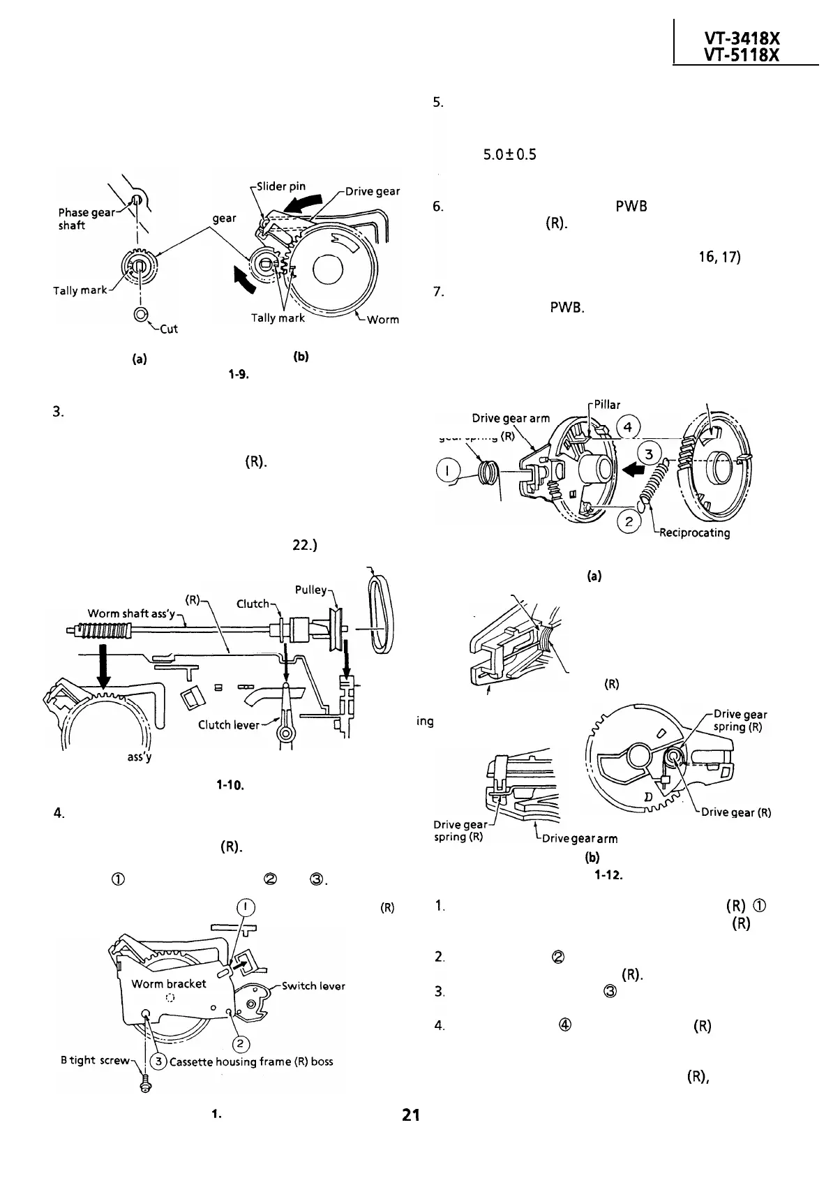
REASSEMBLY OF DRIVE GEAR
rPillar
Worm wheel
square hole
I
Drive gear spring
(R
0
LReciprocating spring
ing
(4
Drive gear arm
,,
1
Drive gear arm
Worm wheel
ass’y
Figure
l-1
0.
4.
Attach the worm bracket to the worm shaft
assembly. Place them onto the boss on the
cassette housing frame
(R).
Note:
Insert
0
before screwing into
Q
and
0.
1
Cassette housing frame
(R)
P
r-3
1.
Drive gear
spring
(R)
spring-shaft
gear
arm
(Drive gear bottom view)
(W
Figure
l-1
2.
Pass the tip of the drive gear spring
(R)
0
through the square hole of the drive gear
(R)
to
hook the spring in position.
Hook one end
Q
of the reciprocating spring to
the catch of the drive gear
(R).
Hook the other end
0
of the reciprocating
spring to the catch of the worm wheel.
Insert the pillar
@
of the drive gear
(R)
into the
square hole of the worm wheel. Turn the worm
wheel somewhat counterclockwise for insertion
of the worm wheel to the drive gear
(R),
because
the reciprocating spring is at work.
Figure l-l
1.
21
 Loading...

