0
1.
2.
3.
4.
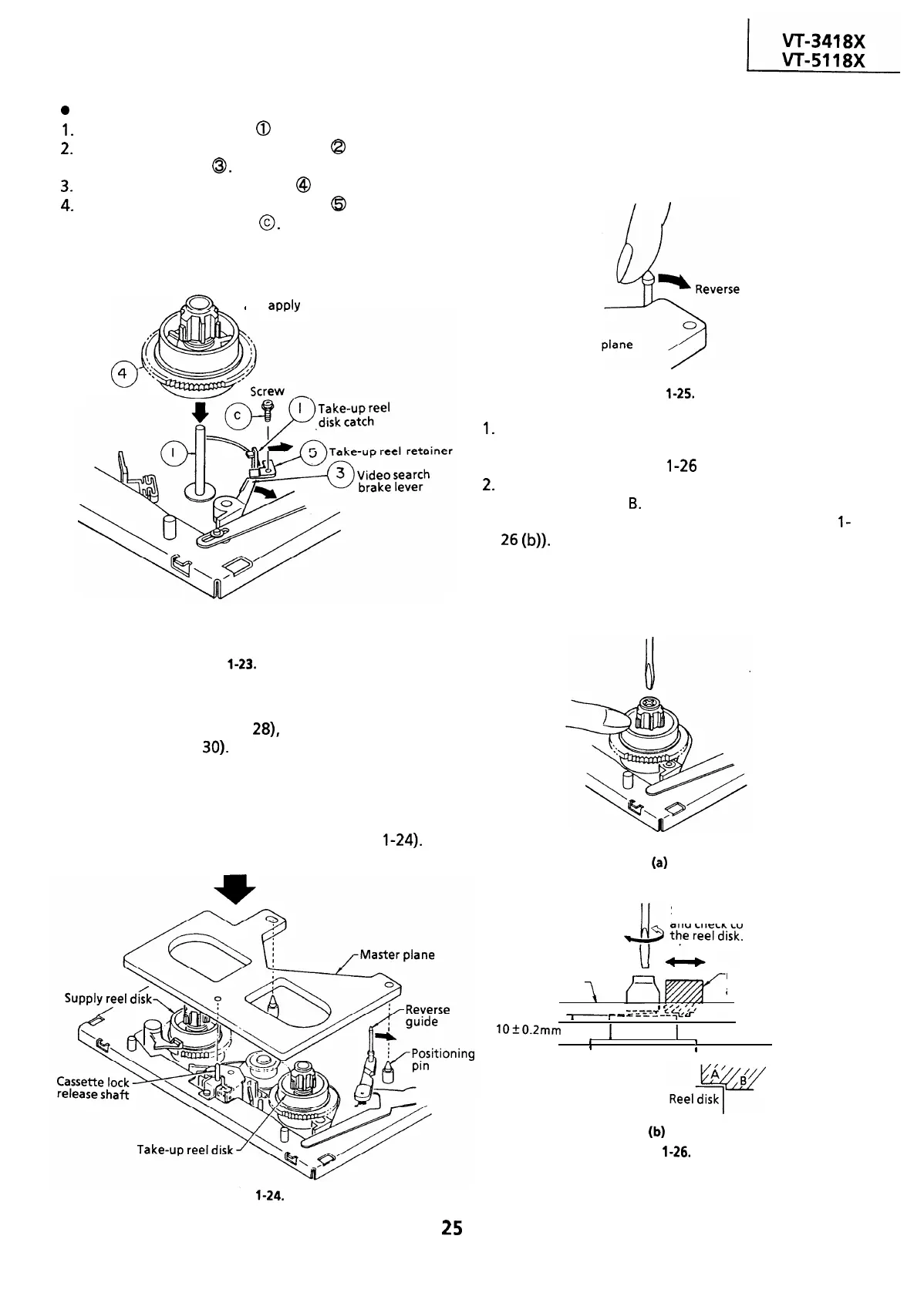
Reassembly (Take-up reel disk)
Clean the reel disk shaft
0
and apply oil to it.
Release the take-up reel catch
@
and video
search brake lever
0.
Install a new take-up reel disk @ onto the shaft.
Replace the take-up reel retainer
@
in position
and tighten up the screw
0.
Note:
Take care not to damage the video search brake
lever.
Clean the reel disk shaft well,
and
aoolv
oil to it.
Take-up
reel disk
Apply a thin tip driver to the arrow position in
releasing for easier setting of the take-up reel disk.
Figure
l-23.
* After reassembly, check the video search rewind
back tension (see page
28),
and check the brake
torque (see page
30).
l
Height checking and adjustment
Note:
Place the master plane onto the mechanism unit,
taking care not to hit the drum (see Figure
l-24).
Setting
Set the master plane releasing
the reverse guide by a finger.
Master
guide
Figure
l-25.
1.
For height adjustment, press the reel disk with a
finger, and turn it right and left with a
screwdriver (see Figure
1-26
(a)).
2.
Check that the reel disk is lower than part A but
higher than part
B.
If the height is not correct,
adjust the height adjusting screw (see Figure
l-
26
(W.
Note:
Whenever replacing the reel disk, perform the
height checking and adjustment.
(4
Slide it right and left,
and check contact with
”
Master plane
Reel disk height
adjusting jig
L
I
f
’
y,
‘,‘, ,
-
r
-
c-c=~Z
“fc
&I-
‘-
lOfO.Zmm
I
1
Reel disk
]
I
/Mechanism chassis
9
0
(b)
Figure
l-26.
Figure
l-24.
25