REPLACEMENT AND HEIGHT CHECKING
AND ADJUSTMENT OF REEL DISKS
1.
2.
3.
a
1.
2.
3.
4.
Remove the cassette housing control assembly.
Set the mechanism in the playback mode with no
cassette tape in place. Unplug the power cord.
Set the idler gear in the center (neutral).
Removal (Supply reel disk)
Remove the tension band
0.
(Take care not to
deform it.)
Unscrew the screw @ and remove the supply reel
retainer assembly
8.
Release the supply reel disk catch
@
and back
tension lever
0.
Pull the supply reel disk upward.
Notes:
1.
Take care not to deform the tension band.
2.
Check and adjust the tension pole position. (See
page 30.)
3.
Be careful not to damage the gear and the idler
gear on the supply reel disk.
4.
Press the tension band in the direction of the
arrow for removal (See Figure
1-20(b)).
Note:
When the tension band is pressed in the direction
of the arrow for removal, the catch is hard to be
deformed.
(b)
Figure
l-20.
0
1.
2.
3.
0
1.
2.
3.
4.
5.
Removal (Take-up reel disk)
Unscrew the screw
@
and remove the take-up
reel retainer.
Release the take-up reel disk catch
0.
Pull the take-up reel disk
@
upward.
Take-up
reel disk
e-up reel
retainer
Figure
l-21.
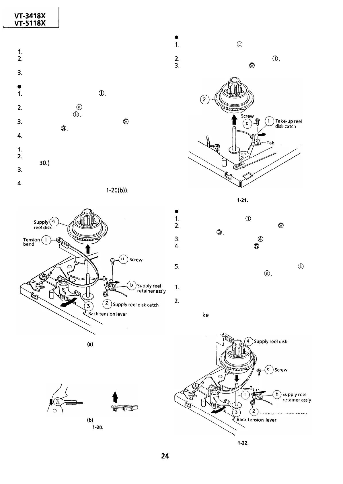
Reassembly (Supply reel disk)
Clean the reel disk shaft
0
and apply oil to it.
Release the supply reel disk catch
Q
and back
tension lever
0.
Install a new supply reel disk
@
onto the shaft.
Replace the tension band
($9
around the supply
reel disk, and insert it to the hole of the tension
arm.
Replace the supply reel retainer assembly
@
in
place, and tighten up the screw
@.
Notes:
1.
2.
Take enough care not to deform the tension
band during installation of the supply reel disk.
Be careful not to damage the supply reel disk
gear, back tension lever, supply reel disk catch,
or the Ii
ke
with tools.
Q
5 Tension band
-.
Supply reel
disk catch
Figure
l-22.
24
 Loading...

