VT-341
8X
VT-5118X
I.
Detach the pinch roller from the capstan shaft.
2.
Set the tension gauge by hooking the tension
gauge adapter onto the pinch roller shaft.
3.
Gradually release the pressure to allow the pinch
roller to touch the capstan shaft. When the
pinch roller just touches the capstan shaft, read
the indication on the gauge.
4.
Check that the reading of the tension gauge is in
the range of
1000
to
1200
g.
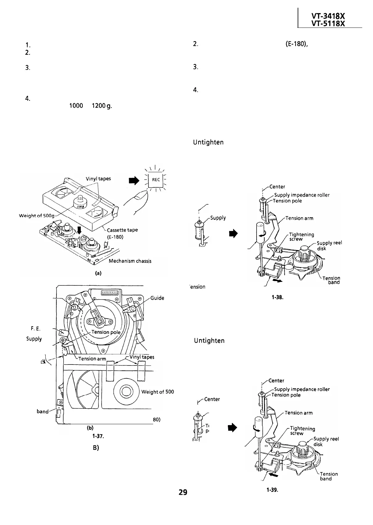
CHECKING AND ADJUSTMENT OF TENSION
POLE POSITION
l
Remove the cassette housing control assembly.
l
Setting
\‘I//
Place the unit in
the record mode.
Guide roller A
F.
E.
head
SUPPlY
impedance.
roller
.Guide
roller B
g-&n
arm&YkPes
Check the left
side position
(by sight).
T
500
g
Tension
band’m
1
and plate
adjusting jig
setting hole
l
Checking
Video Cassette tape (E-l
80)
b)
Figure
l-37.
I. The guide rollers (A,
B)
operate to bring the tape
outside the cassette tape and simultaneously the
tension pole moves to the left, loading the tape.
At that time (loading completed), check the
position of the tension pole.
2.
At the beginning of the tape
(E-180),
check that
the tension pole’s left side is aligned with the
supply impedance roller’s center by sight.
3.
Check that the end of the tape is neither curled
against the flange of the supply impedance
roller nor over it.
4.
During the video search rewind mode with no
cassette tape in place, check that the supply reel
disk is free from the tension band.
l
Position adjustment (record mode)
When the tension pole is at the right of the supply
impedance roller’s center:
Untighten the tightening screw, and shift the
tension band adjustment bracket in the direction of
the arrow using a tension band and plate adjusting
Jig until it is in the set value range (center). Then
secure it with the tightening screw.
(Center
Center
I
:
/-SUPPlY
impedance
roller
Tension
pole
I)
Tension band
and plate
adjusting jig
‘ension band adjustment bracket
Figure
l-38.
l
Position adjustment (record mode)
When the tension pole is at the left of the supply
impedance roller’s center:
Untighten the tightening screw, and shift the
tension band adjustment bracket in the direction of
the arrow using a tension band and plate adjusting
Jig until it is in the set value range (center). Then
secure it with the tightening screw.
/enter
<Center
I
I
lir
Supply impedance
roller
!
Tension
a
pole
I)
Tension band
and plate
adjusting jig
Tension band adjustment bracket
Figure
l-39.
 Loading...

