W-341
8X
I
c
W-5118X
1
0
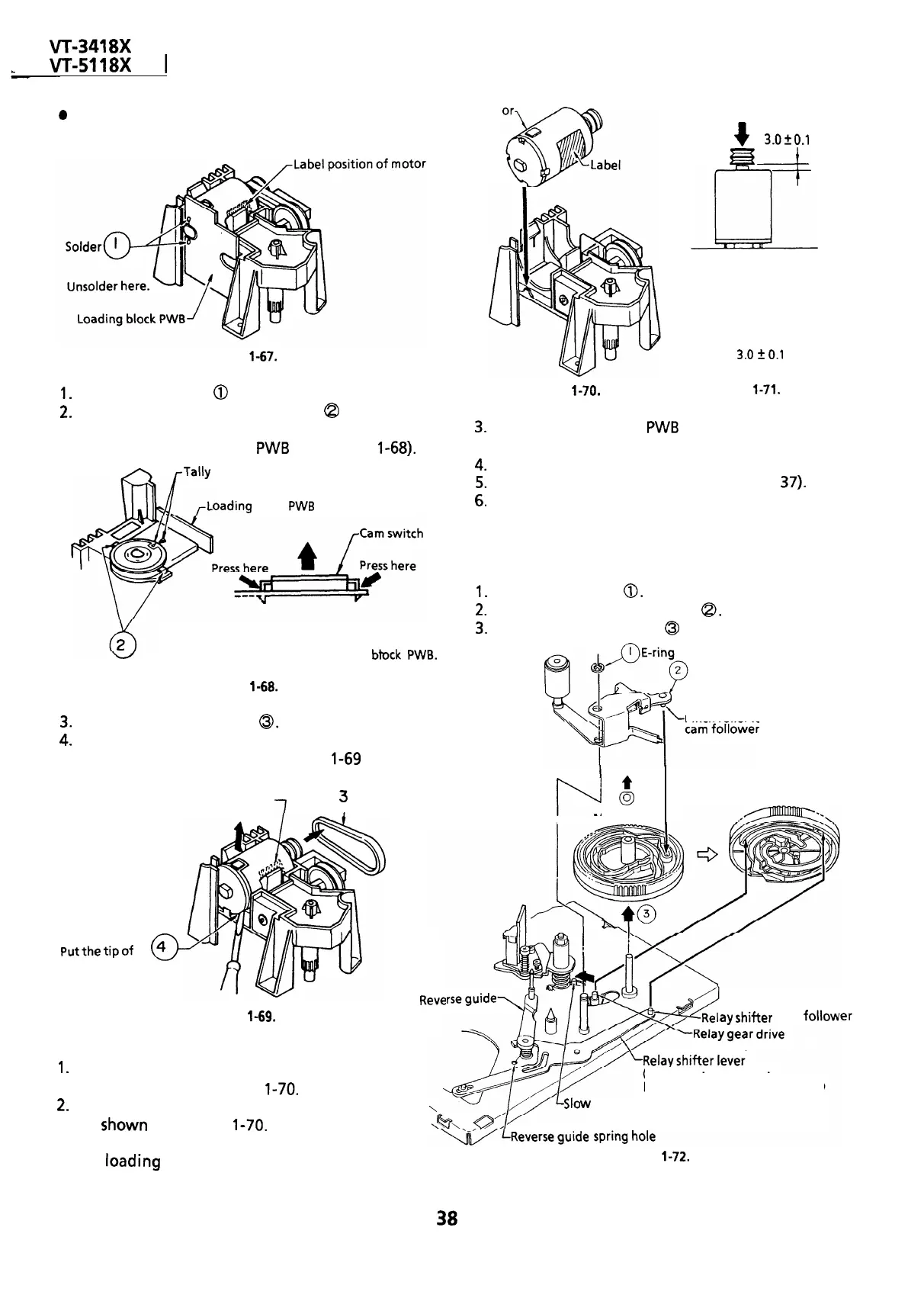
Removal
Loading mot
Figure
l-67.
1.
Unsolder the leads
0
from the loading motor.
2.
Unlock the left and right catches
Q
of the cam
switch off the loading block. Take out the cam
switch and loading block
PWB
(See Figure
l-68).
,-Tally
marks
oading
block
PWB
Pull up the cam switch pressing
the catches. Remove the cam switch
Catches of cam switch
together with the loading btock
PWB.
Figure
l-68.
3.
Take out the loading belt
0.
4.
Pry up the back end of the loading motor with a
screw driver or the like as in Figure
l-69
and take
out the motor.
Motor label
7
Q
3
Loading belt
putthetipof
a
4
0
screwdriver or the
like here. Pry UP the
back end of the
loading motor and
Reve
take out the motor.
Figure
l-69.
ay
shifter
cam
fOllOW
3.
Set the loading block
PWB
and the cam switch in
position.
4.
Resolder the leads to the loading motor.
5.
Finally place the loading block (See page
37).
6.
Attach the loading belt.
Figure
l-70.
+
3.0fO.l
mm
33
=I
IilL
Note:
When press-fitting the loading
motor pulley, keep the pressure
less than 5 kg, and the gap
between the motor and pulley
should be
3.0
2
0.1
mm.
Figure
l-71.
REPLACEMENT OF MASTER CAM
l
Removal
1.
Remove the E ring
0.
2.
Remove the pinch roller lever
a.
3.
Pull out the master cam
0
upward.
Pinch roller lever
Pinch
roller lever
I
t
P
0
I
Master cam
Bottom side of
master
cam
l
Reassembly
1.
Remove the loading motor, and mount a new
loading motor as in Figure
l-70.
lever cam follower
(Place the relay shifter
lever to the unloading position.)
2.
Place the loading motor so that its label is visible
\
as
shown
in Figure
l-70.
Make sure that the
screw hole at the motor shaft, protuberance *on
the
bading
block, and the motor’s back end
marked with the arrow are mated with each
other.
38
w
brake lever cam follower
Figure
l-72.
ler
 Loading...

