VT-341
8X
VT-5118X
1.
2.
3.
4.
5.
Remove the slow brake spring
0.
Remove the washer
@.
Remove the slow brake lever
0.
Remove the E ring
@.
Rotate the take-up loading gear, take-up
loading arm assembly, supply loading gear and
supply loading arm assembly slightly in the
loading direction, and take them
@
all out.
Remove the E ring
8.
Remove the relay gear drive lever
@.
Reassembly
Reverse the procedure. Be sure to match the
tally marks on the gears.
6.
7.
0
Notes:
Figure
l-64.
1.
2.
3.
4.
5.
When reassembling, apply specified grease to
the following points; all the gear teeth, all the
gear shafts and the cam groove of loading relay
gear.
Be careful not to deform the supply/take-up
loading arms.
Be careful to keep clean the slow brake lever felt.
Be also careful to keep the outer surface of the
capstan
D.D.
motor free from dust and dirt. (If
stained, the MR (Magnet Resistor) element
might be damaged.)
Take care not to deform the anti-fall hooks of
the slow brake lever, slow brake shaft cap and
supply/ take-up loading gears more than
required.
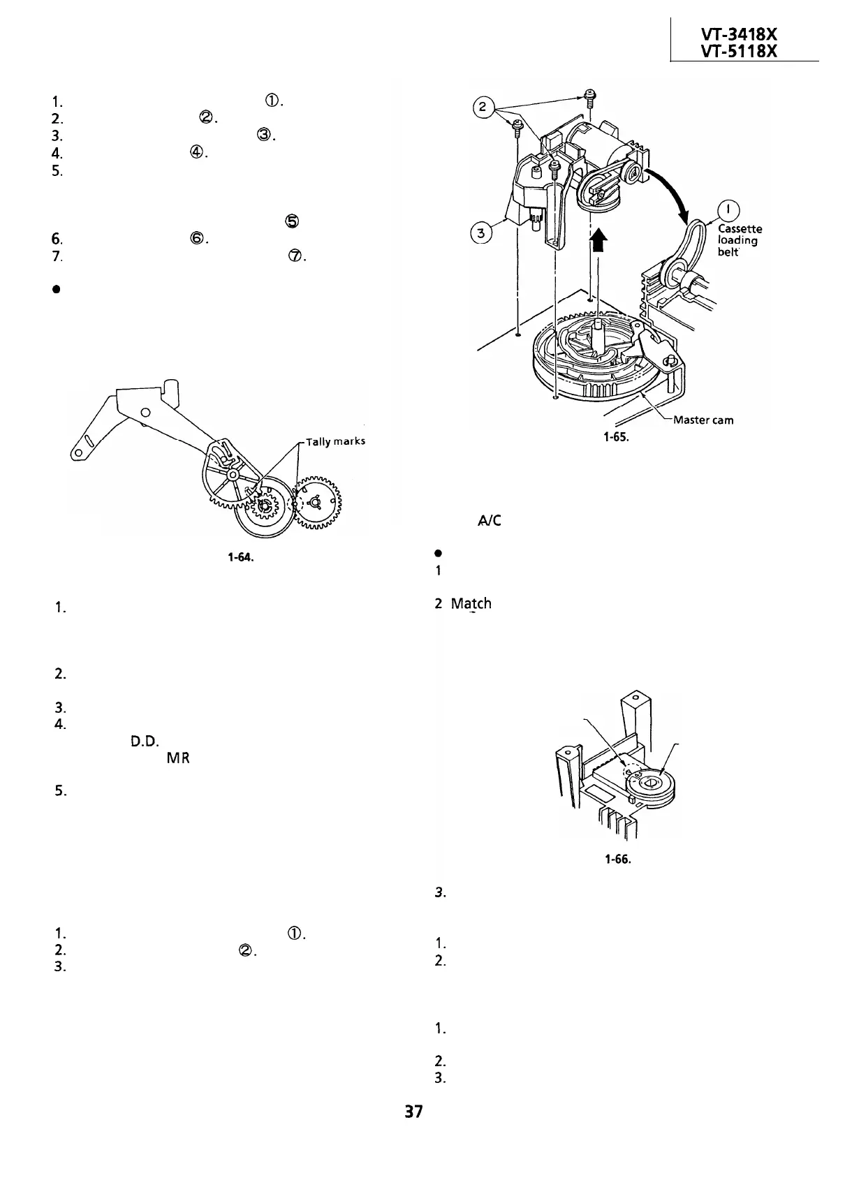
REMOVAL AND REASSEMBLY OF LOADING
BLOCK
l
Removal
1.
Remove the cassette loading belt
0.
2.
Unscrew the three screws
Q.
3.
Pull the loading block upward.
Screws
Figure
l-65.
Note:
When using a magnetic screw driver in removal of
three screws, do not allow the magnetic driver to
hit the A/C head or drums.
Reassembly
Turn the master cam all the way counter-
clockwise.
Ma_tch
the tally mark on the cam switch with the
matching mark.
Fit the loading block and the
master cam with each other. Tighten up the
three screws.
Tally mark
Cam switch
Figure
l-66.
4.
Finally connect the leads and apply the cassette
loading belt.
Notes:
1.
Be careful not to scratch the gear.
2.
Be careful not to stain the belt. If dirty, clean it
up with the specified cleaning liquid.
REPLACEMENT OF LOADING MOTOR
1.
Set the cassette ejected condition by placing the
unit in the cassette eject mode.
2.
Unplug the power cord.
3.
Remove the loading block in accordance with
the statements and drawings above.
37
 Loading...

