VT-341
8X
VT-5118X
f)
Push the
(+)
or (-) tracking button to check
that a flat response is obtained on the
envelope waveform.
g)
Secure the guide roller by tightening the
guide roller setscrew in the unloading mode.
h)
Play back the tape drive train alignment tape
to check that the envelope waveform does
not change.
c)
Adjust the playback switching point.
d)
Check the flatness of the envelope waveform
and sound by playing back a recorded tape.
8.
Adjustment of A/C head X-position.
a) Push the (
+)
and
(-)
tracking buttons at the
same time to the preset mode.
b)
Rotate the X-position adjusting nut with an
adjusting box driver, and adjust the
A/C
head
position for maximum head switching pulse
low side envelope.
X-position adjusting
nut
1-2
mm
Main
chassis
Figure
l-60.
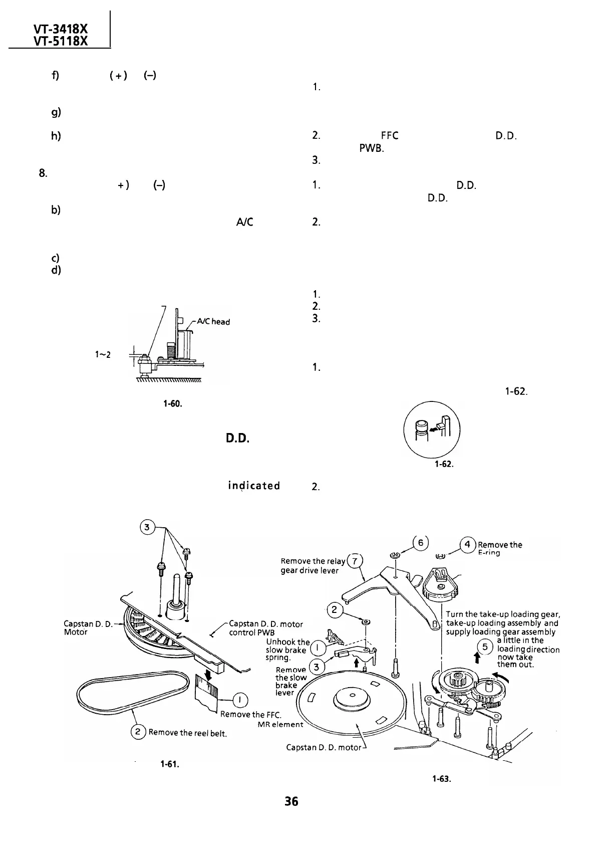
REPLACEMENT OF THE CAPSTAN D.D.
(DIRECT DRIVE) MOTOR
l
Remove the cassette housing control assembly.
l Removal (Follow the order of
ingicated
numbers.)
Remove the three screws.
l
Reassembly
1.
Mount the capstan motor on the mechanism
chassis making sure not to allow the capstan
shaft to hit the mechanism chassis, and attach it
with the three screws.
2.
Insert the
FFC
into the capstan
D.D.
motor
control
PWB.
3.
Attach the reel belt.
Notes:
1.
After installing the capstan
D.D.
motor, be sure
to rotate the capstan
D.D.
motor and check the
movement.
2.
Check and adjust the servo circuit.
REMOVAL AND REASSEMBLY OF THE
LOADING GEAR BLOCK
1.
Remove the cassette housing control assembly.
2.
Remove the reel belt.
3.
Remove the reel block.
Notes:
l
Removal
Notes:
1.
Use care not to deform the parts hooked to the
slow brake shaft cap, take-up loading gear and
supply loading gear as shown in Figure
l-62.
Figure
l-62.
2.
in removing the loading gear, secure the guide
roller with a rubber band or the like beforehand
for easier reassembly.
Remove the E-ring
Loading relay gear
Remove the washer
Figure 1-61.
Figure
l-63.
36
 Loading...

