VT-341
8X
VT-51
18X
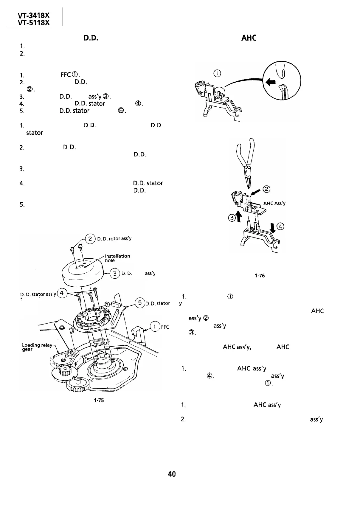
REPLACEMENT OF D.D. MOTOR
l-
Put the unit in the cassette eject position.
2.
Unplug the power cord.
point.
setscrew
positioning
rotor
ass’y
REPLACING THE
AHC
(AUTOMATIC HEAD
CLEANER)
l
Removal (Reverse the order in reassembly.)
1.
Remove the
FFC
0.
2.
Remove the two
0.0.
rotor assembly setscrews
a.
3.
Pull out the
0.0.
rotor
ass’y
0.
4.
Remove the three
0.0.
stator setscrews
@.
5.
Remove the
0.0.
stator assembly
@.
Notes:
1.
When removing the
0.0.
rotor assembly or
0.0.
stator
assembly, use care not to hit the loading
relay gear.
2.
Secure the
0.0.
rotor assembly so that the
installation positioning holes in the
0.0.
rotor
assembly and lower drum assembly match.
3.
Be careful not to damage the upper drum or the
video head.
4.
Be sure that the hall device and the
0.0.
stator
assembly are not damaged by the
0.0.
rotor
assembly or other parts.
5.
After installation, adjust the playback switching
setscrew
D.
D.
stator
ass
FFC
Figure
l-76
l
Removal
1.
Unhook pat-t
0
with a finger in the direction of
,
Y
arrow.
Hold the rib (marked with an arrow) of the
AHC
ass’y
Q
with electrician’s pliers or the like, and
pull the
ass’y
upward in the direction of arrow
0.
Note:
To pull out the AHC
ass’y,
hold the AHC lever down.
l
Reassembly
I.
Push down the
AHC
ass’y
in the direction of
arrow
@.
Make sure that the
ass’y
is secured in
position by the hook of part
0.
Figure
l-75
Notes:
1.
Be careful to keep the
AHC
ass’y
out of contact
with the drum.
2.
Be careful to keep the cleaner section of the
ass’y
free of grease of contaminants.
40
 Loading...

