ADJUSTMENT OF THE
VCR ELECTRICAL CIRCUITRY
Notes:
Q
Before the adjustment:
Electrical adjustments discussed here are often required after replacement of electronic
components
and
mechanical parts such as video heads.
Check that the mechanism and all electric components are in good working condition prior to the
adjustments, otherwise adjustments can not be completed.
l
Instruments required:
@Audio
signal generator
@
Dual-trac
e oscilloscope
@AC
milli-voltmeter
@
Frequency counter
@
Blank video cassette tape
0
Screwdriver for adjustment
@Colour bar generator
@DC
voltmeter
@Alignment tape
(VROCPSV)
@
Extension connector
(QCNW-3778CEZZ:
AB
-
AB)
(QCNW-3780CEZZ:
AL
-
AL)
n
SERVO CIRCUIT ADJUSTMENT
Adjustment of head switching point
Measuring
Dual-trace oscilloscope
instrument
Mode
Cassette
Test point
Playback
Alignment tape
(VROCPSV)
VIDEO OUT (pin
(3)
of EL
connector) to
CH
1
TP2202
(Trigger) to
CH2
(Located on the Y/C
PWB)
Control
R7701
head switching point
adjustment control
Specification
6.5
2
0.5
H (lines)
1.
Play the alignment
tape.(VROCPSV.)
2.
Short circuit test points
TP8201
and
TP8202
on
the A/V Jack
PWB
or remove the cassette
housing
ass’y
to set the auto tracking to center.
(See Note below)
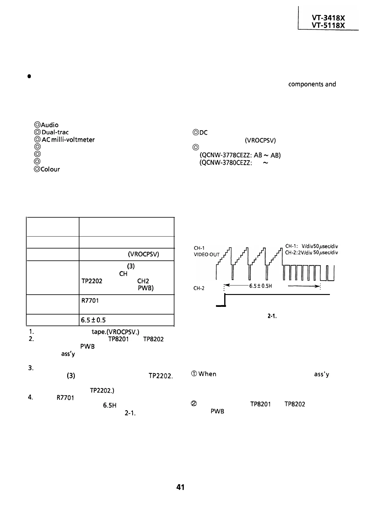
3.
Connect a dual trace oscilloscope to the VIDEO
OUT (pin
(3)
of EL connector) and TP2202.
(Trigger the oscilloscope with the head
switching pulse on TP2202.)
4.
Adjust
R7701
so that the leading edge of the
head switching pulse is 6.5H (lines) ahead of the
vertical sync as shown in Figure
2-1.
CH-1: 1
V/div
50pseddiv
CH-2:2V/div
50peddiv
CH-2
i(
HEAD .
SWITCHING
PULSE
-
6.5
2
0.5H
(lines)
-;
V-sync.
Figure
2-1,
Notes:
To make this adjustment, disable the AUTO
TRACKING function.
The AUTO TRACKING function is disabled in the
following cases.
(In the playback mode only.)
@When
the cassette housing control
ass’y
is
removed, press both tracking control buttons of
the remote control unit at the same time to set
the tracking in center.
Q
When test points
TP8201
and
TP8202
on the A/V
jack
PWB
are short-circuited.
41
 Loading...

