WTest
points
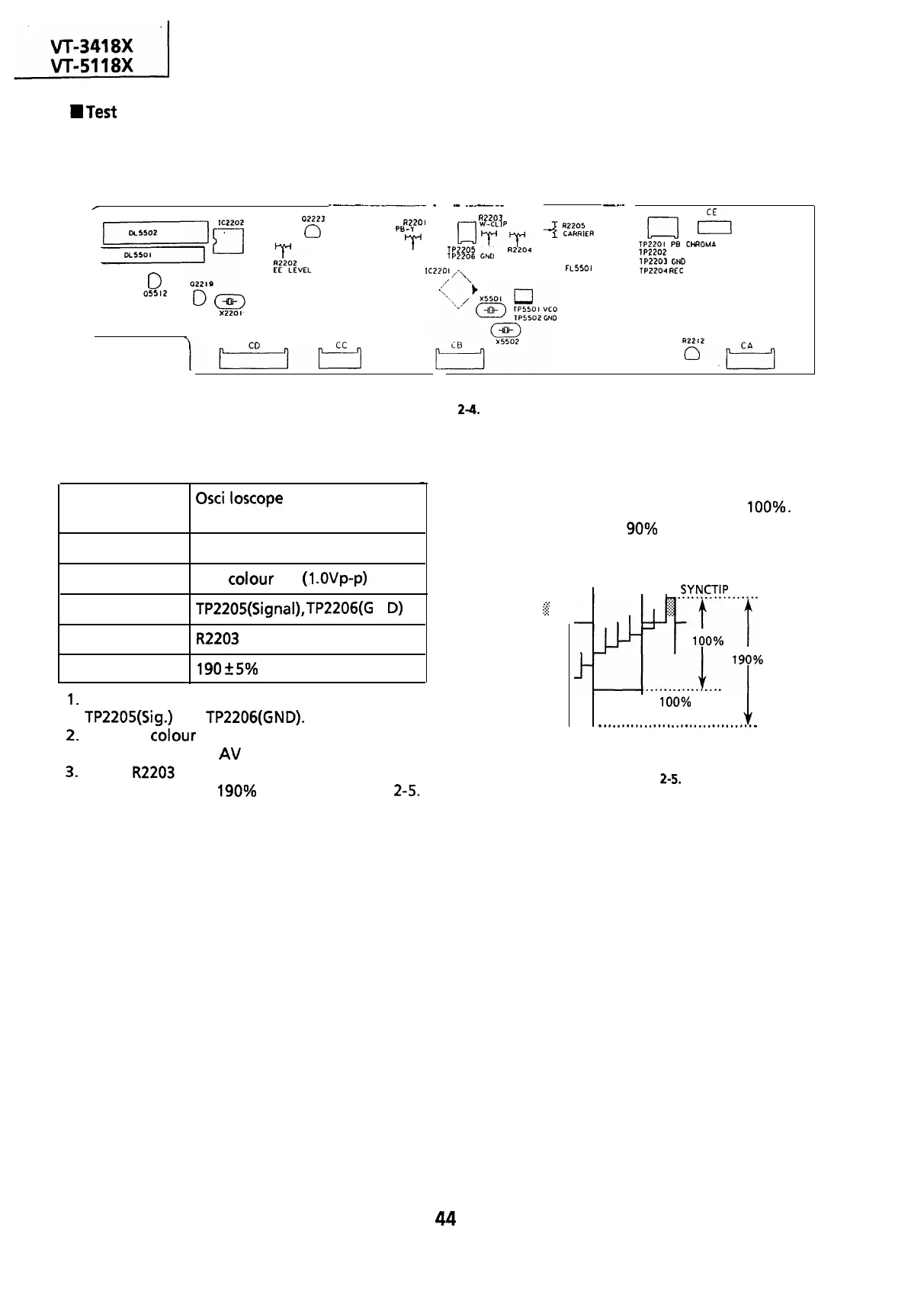
layout of Y/C Unit.
---___-
_
.-
_-_---
----
__.-
r
0
05512
02223
0
R2201
A2203
PB-Y
LEVEL
GJ
yyPT
TP2205
CLIP
R2204
lP2206
C&D
DEVIATION
IC220
I,^\
FL5501
cl
El
TP2201
PB CHROMA
lP2202
HEAD SWITCHING PULSE
lP2203
GND
TP2204
REC SIGNAL
Figure
2-4.
Adjustment of white clip
-
Measuring
instrument
Mode
Input signal
Test point
Control
Specification
Osci
I loscope
E-E or Record
PAL colour bar
(1
.OVp-p)
TP2205(Signal),
TP2206(G
N
D)
R2203
white clip control
190
+
5% (See note below)
1.
Connect the oscilloscope to test points
TP2205(Sig.)
and
TP2206(GND).
2.
Feed the
colour
bar signal to the VIDEO IN jack
and put the unit in
AV
input mode.
3.
Adjust
R2203
so that the overshoot of the video
signal is clipped at 190% as shown in Figure
2-5.
Note:
From sync tip to white peak, the level is
100%.
The white clip level is
90%
above the white level.
(There is no dark clip adjustment.)
.
. .
.
.:.:
$2
l-
I
I
SYNCTIP
I
100% WHITE
-.................................w
WHITE CLIP LEVEL
Figure 2-5.
44