Adjustment of FM carrier frequency and
deviation
Measuring
instrument
Mode
Input signal
Test point
Frequency counter
Oscilloscope
Record/Playback
PAL colour bar
(1
.OVp-p)
TP2204
VIDEO OUT
(pin
(3)
of EL connector)
Control
R2205
FM carrier control
R2204
Deviation control
Specifications
3.8
,+
0.05MHz
2.0
+,
O.lVp-p
1.
Be sure that R2202 (E-E LEVEL) has been
correctly adjusted.
2.
Connect an oscilloscope to the VIDEO OUT (pin
(3)
of EL connector).
3.
Connect a frequency counter to test points
TP2204.
4.
Put the unit in
AV
input mode. Do not feed any
signal to the VIDEO IN jack. (Disconnect any
cable from video input terminal.)
5.
Under this condition, adjust
R2205
so that the
frequency counter reads
3.8MHz.
6.
Feed the PAL standard
colour
bar signal to the
VIDEO IN jack and adjust
R2204
so that the
frequency counter reads
4.3MHz.
7.
Repeat step 5
thru
7 a few times.
8.
Under this condition record the
EIA
colour
bar
on tape, rewind and playback.
9.
Make sure that the amplitude of the playback
colour
bar signal is
2.0
kO.1
Vp-p as shown in
Figure
2-6.
If it is out of specified value, check
the PLAYBACK LEVEL
(R2201)
and retry this
adjustment.
Adiustment
of playback level
Measuring
instrument
Mode
Cassette
Test point
Control
Specifications
Osci
I
loscope
Playback
Alignment tape
(VROCPSV)
VIDEO OUT
(pin
(3)
of EL connector)
R2201
playback level control
2.0
i
0.2
vp-p
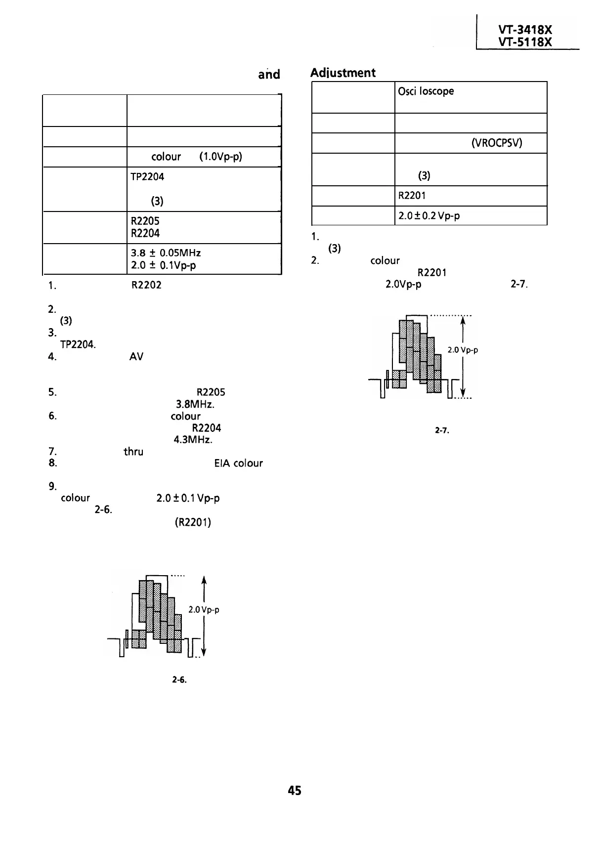
1.
Connect an oscilloscope to the VIDEO OUT (pin
(3) of EL connector).
2.
Play the
colour
bar portion of the alignment
tape and adjust
R2201
so that the signal
amplitude is
Z.OVp-p
as shown in Figure
2-7.
Figure 2-7.
. . . . . . . . .
t
2.0
vp-p
lr
1
. . . . . .
Figure
2-6.
45
 Loading...

