VT-341
8X
VT-51
18X
n
AUDIO CIRCUIT
Checking of audio play-back level
Measuring
instrument
AC milli-voltmeter
I
Mode
I
Playback
I
Input signal
Alignment
tape.(VROCPSV)
(1
kHz level adjusting signal.)
Test point
AUDIO OUT
(pin
(7)
of EL connector)
I
Specification
1
-
9
+
2dBs
(0.6-l
.OVp-p)
I
1.
Playback the Alignment tape.
(VROCPSV
1
kHz
level adjusting signal)
2.
Connect an AC
milli-voltmeter
to the AUDIO
OUT (pin
(7)
of EL connector).
3.
Make sure that the output level is
-
9
+
2dBs.
Checking of audio record level
Measuring
AC
milli-voltmeter
or
instrument
Osci
I
loscope
I
Mode
I
Record/Playback
I
I
Input signal
I
1
kHz,
-8dBs
(0.87Vp-p)
I
Test point
AUDIO OUT
(pin
(7)
of EL connector)
1
Specification
1
-8
f
2dBs(0.7-l.lVp-p)
I
1.
Connect an AC
milli-voltmeter
to the AUDIO
OUT (pin
(7)
of EL connector).
2.
Feed the audio signal shown in
tableto
the
AUDIO IN jack.
3.
Make the self-recording and playback of the
signal.
4.
Make sure that the AUDIO OUT level is as
specified. If it is out of specified value, verify
the bias current (ADJUSTMENT OF AUDIO BIAS
CURRENT below).
Adjustment of audio bias current
I
Measuring
I
AC
milli-voltmeter
or
.
instrument
Oscilloscope
I
I
Mode
I
Record
I
Input signal
Test point
Control
Specification
Not required
TP660 1 ( + )
-
TP6602(
-
)
R6634
2.6
+
0.1
mVrms
(7.6
+
0.3mVp-p)
1.
Connect an AC milli-voltmeter to test points
TP6601(
+ ) and
TP6602(
-).
(Use
TP6602
for ground lead.)
2.
Set the unit in recording mode.
3.
Adjust
R6634
so that the signal amplitude is
2.6mVrms.
Checking of erase voltage and oscillation
freauencv
I
Control
I
T660
1
I
I
Specification
I
70
f
SkHz,
4OVp-p
or greater
I
1.
Put the unit in record mode.
2.
Connect an oscilloscope across the full erase
head.
3.
Make sure the erase voltage across the full
erase head is
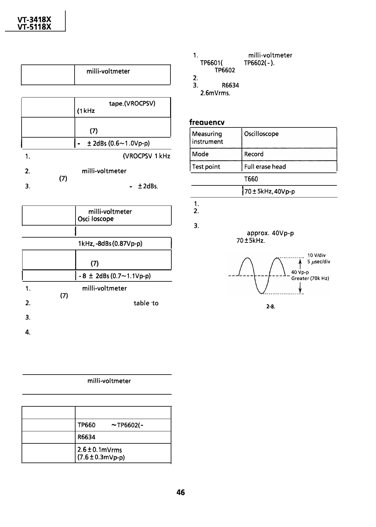
approx.
4OVp-p
or more and
frequency is
70
+
5kHz.
Figure 2-8.
 Loading...

