n
I
1
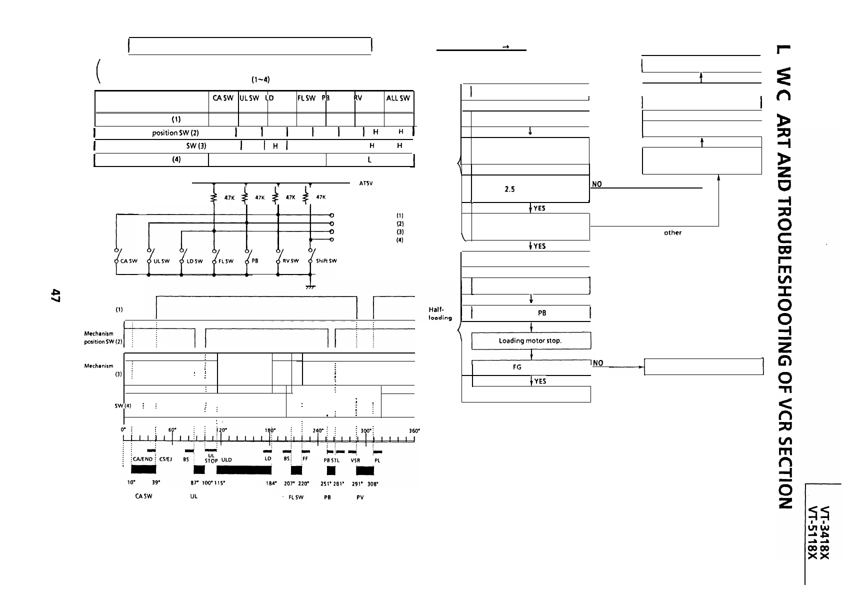
MECHANISM OPERATION FLOWCHART
1
CASSETTE INSERTION -+ STOP
0
z
l This flowchart describes the outline of the mechanism’s operation, but does not give its details.
l Function of cam switch bit reading.
The on/off of cam switch is cam position switch
(l-4)
input signals in conditions as shown in below.
End
I
I
J
t
I
1
Insert cassette.
I I
Cassette is ejected and loading
I
n
CASW
ULSW
CD
SW
FLSW
PE
SW
RV
SW
ALLSW
‘ON’
‘ON’ ‘ON’
‘ON’
‘ON‘
‘ON’
‘OFF’
Mechanism position SW (1) input
L
H H H H
L
H
I
1
t
,
I
motor stops.
1
I
b
Turn off cassette switch.
I
t
J
Cassette switch turns on.
I
I
1
I
1
Mechanism
positionSW(2)
input
1
H
1
L
1
H
1
H
1
L
I
H
I
H
1
1
Mechanism position
SW(j)
input
I
H
I
H
I
L I L I H I
H
I
H
I
Loading motor starts in normal
t
direction and master cam clockwise.
Loading motor turns in reverse
direction and master cam
t
counterclockwise.
Does cassette control clutch come
off within 2.5 sec. after cassette
ND
t
A
switch has turned off?
(Cassette is judged caught halfway.)
Mechanism position SW
(4)
input
H H H
L L
c
H
Cassette
inserting
T
1 T
T
ATSV
f
47K
+
47K
4
47K
$
47K
L
1
tYE5
Are start/end sensors at low level
before cassette insertion?
NO
+YES
(Cassette LED or some
judged defective.)
input
input
input
Input
i)
Mechanism position SW
(1)
0
Mechanism position SW (2)
0
Mechanism position SW (3)
Mechanism position SW (4)
PB
SW
part is
\
I
Drum motor starts.
I
t
Pinch roller comes into contact.
i
Mechanism
position SW (1)
h
1
Cam switch is at
PB
position.
1
Mechrnirm
position
sw(2)
/I
//
-j
Mechanam
!
position SW
(3)
i
Mechanism
position
SW(4)
i
i
.
i
:
;
:
:
:
i
: :
. .
.
i
,
: : :
: : :
:
;
:
:
:
i
. : :
. .
: :
:.
. .
. .
. .
: :
:
;
:
:
:
:
:
:
:
:
. .
: : :
;
: :
. ,
: .
: :
: :
: :
:
:
:
*
. Shift zone
i
: :
*
i
;
i
.
: .
:
i
: :
: :
. .
Is drum
FG
pulse outputted?
.I0
Unloading
I
IYES
I
End
CAM SW
CASW
UL SW
CD SW
Pa
SW
PV
SW
 Loading...

